Audi Q3: A/C Compressor Regulator Valve -N280-, Checking Switch-On Signal
Special tools and workshop equipment required
- Vehicle Diagnostic Tester
- Connector Test Set -VAG1594D-
- Probe -VAS5051/8-
Test Sequence
- Remove the noise insulation. Refer to → Body Exterior; Rep. Gr.66; Noise Insulation; Noise Insulation, Removing and Installing.
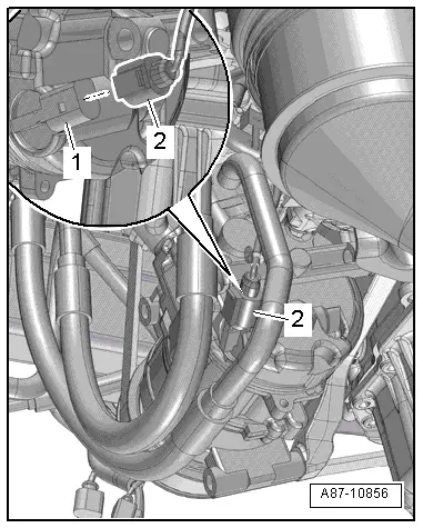
- Disconnect the connector -2-.
- Re-establish the connection between the connector -2- and the A/C Compressor Regulator Valve -N280--item 1- using an adapter cable from the Connector Test Set -VAG1594 D-.
 Note
Note
- The activation of the A/C Compressor Regulator Valve -N280- and the current measured by the Climatronic Control Module -J255-/A/C Control Module -J301- control head, which flows via the A/C Compressor Regulator Valve -N280-, is displayed in the control head measured values. "Read measured values" using the Vehicle Diagnostic Tester in the "Guided Fault Finding" function.
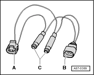
- An adapter cable can also be used for this test. To do this, for example, use one connector each -A- and -B- (part number 1J0 973 702 and 1J0 973 802 and related terminal contacts; refer to the Parts Catalog), two commercially available sockets for banana connectors -C- and two wires with 0.5 mm 2 diameter.
- Connect the Probe - VAS5051/8- to the adapter cables.
- Measuring cable (signal wire) to contact "2" of connector -2-.
- Measuring cable (shielding, ground) to contact "1" of connector -2-.
- Set the operating mode "measuring equipment" DSO (digital storage oscilloscope) on the Vehicle Diagnostic Tester.
- Select the setting 5V/Div = 0.5 ms/Div (5 V DC and 0.5 milliseconds per unit).
- Start the engine.
- Set the temperature preset for the driver- and front passenger side to "Lo" on the Climatronic Control Module -J255- control head. By pressing the buttons Auto and AC or A/C, the activation of the A/C Compressor Regulator Valve -N280- is switched on and off.
- Set the temperature knob to the "cold" stop on the A/C Control Module -J301- control head. By pressing the button AC or A/C, the activation of the A/C Compressor Regulator Valve -N280- is switched on and off.
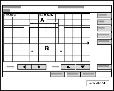
The following is displayed on the oscilloscope screen depending on the control head setting:
- There is no square-wave signal when "OFF" mode is selected (indicator lamp in the AC or A/C button does not illuminate) (the A/C Compressor Regulator Valve -N280- is not activated).

- During "Auto" mode (only automatic climate control system) and the AC or A/C button pressed (indicator lamp in the AC or A/C button illuminates), there is a square-wave signal with an impulse width -A- between 75 % and 100 % (the A/C Compressor Regulator Valve -N280- is activated).
 Note
Note
- The illustration shows a signal with a duty cycle of approximately 80 %.
- The impulse width -A- depends on the desired cooling output, the electrical system voltage, etc. (over the width of region -A-, the current is regulated via the A/C Compressor Regulator Valve -N280- by the Climatronic Control Module -J255-/A/C Control Module -J301- control head).
- The signal distance -B- is always 2 milliseconds. This corresponds to frequency of 500 Hertz.
- The duty cycle is determined by the ratio of impulse width -A- and signal distance -B-.
- The impulse width of the square-wave signal changes depending on the Climatronic Control Module -J255-/A/C Control Module -J301- control head setting and the measured ambient influences (duty cycle between 100% and larger than 30%, the A/C Compressor Regulator Valve -N280- is activated so that the necessary compressor output to reach the specified temperatures is achieved).
 Note
Note
- With the setting, for example, "Auto" mode (automatic climate control system), temperature setting "Lo" and the AC button pressed (indicator lamp in the AC button illuminates), the A/C Compressor Regulator Valve -N280- is activated so that the maximum permissible current of approximately 0.65 A flows via the A/C Compressor Regulator Valve -N280- (maximum compressor output).
- In control mode, actuation time is governed by required cooling output and vehicle electrical system voltage, for example. It is however always of sufficient duration to achieve a mean current of 0.3 A.
- Certain functions on the A/C Compressor Regulator Valve -N280- (for example, a stuck valve or a disruption in the coil) can lead to a complaint regarding the A/C compressor (A/C system doesn't cool, the evaporator ices over, etc.). If the cause is with the A/C Compressor Regulator Valve -N280- (and not the A/C compressor itself), the A/C compressor can be serviced by replacing the A/C Compressor Regulator Valve -N280-. Refer to → Refrigerant R134a Servicing; Rep. Gr.87; Refrigerant Circuit Components, Replacing (Refrigerant R134a, Servicing; Refrigerant Circuit Components, Replacing).
- The A/C Compressor Regulator Valve -N280- is not available as a replacement part for all A/C compressors. If the A/C Compressor Regulator Valve -N280- is not available as an individual A/C compressor part (different versions), then the entire A/C compressor must be replaced. Refer to the Parts Catalog.
High Pressure Sensor -G65-, Checking Pressure Signal
 Note
Note
- The cooling output cannot be checked when the High Pressure Sensor -G65- is removed. The Climatronic Control Module -J255-/A/C Control Module -J301- control head does not switch on the Air Conditioning (A/C) compressor. "Read measured values" using the Vehicle Diagnostic Tester in the "Guided Fault Finding" function.
- After switching off the A/C compressor in this vehicle, it may take a relatively long time for the pressure on the high pressure side to decrease. This is because the expansion valve is cold and the pressure on the low pressure side increases quickly after shutting the compressor off, then the expansion valve closes and the refrigerant flows slowly to the low pressure side.
Test Sequence
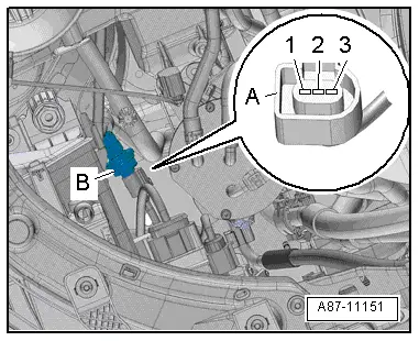
- Disconnect the connector -A-.
Routing of 3-pin connector on High Pressure Sensor -G65-
1 - Ground
2 - Signal output - square-wave signal to the Climatronic Climatronic Control Module -J255-/A/C Control Module -J301- A/C control head
3 - Terminal "75" (positive)
 Note
Note
- With the connector disconnected, the A/C compressor is not switched on.
- The High Pressure Sensor -G65--B- is an electronic control module, which creates a square wave signal, whose duty cycle ratio changes with the pressure in the refrigerant circuit.
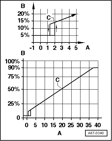
The pressure signal from the High Pressure Sensor -G65-
A - Pressure on the high pressure side of the refrigerant circuit in bar (absolute pressure)
B - Square-wave signal duty cycle
C - Characteristic curve for the square-wave signal duty cycle
 Note
Note
- The Climatronic Control Module -J255-/A/C Control Module -J301- control head switches the A/C compressor on as soon as there is no A/C compressor shut-off condition (by activating the A/C Compressor Regulator Valve -N280-). Refer to Vehicle Diagnostic Tester in the "Guided Fault Finding" function.
- The A/C control head switches the A/C compressor on at a duty cycle larger than approximately 12% (corresponds to approximately 1.2 bar (17.4) absolute pressure) and less than approximately 78% (corresponds to approximately 32 bar (464 psi) absolute pressure), if no other shut-off condition is in effect.
- If the duty cycle is greater than 12% (corresponding to approximately 1.2 bar (17.4) absolute pressure) and less than 78% (corresponding to approximately 32 bar (464 psi) absolute pressure).
- The A/C compressor is not switched on if the duty cycle is smaller than 12% or greater than 78% (the A/C Compressor Regulator Valve -N280- is not activated).
- The duty cycle and the pressure calculated by the Climatronic Control Module -J255-/A/C Control Module -J301- are displayed as a measured value. Refer to Vehicle Diagnostic Tester in the "Guided Fault Finding" function.
- In terms of absolute pressure, 0 bar corresponds to an absolute vacuum. Normal ambient pressure equals approximately 1.0 bar (14.5 psi) absolute pressure. 0 bar pressure corresponds to an absolute pressure of approximately 1.0 bar (14.5 psi) on most pressure gauge scales (indicated by "-1" below "0").
- Depending on the calculated refrigerant circuit pressure with the A/C compressor activated, the Climatronic Control Module -J255-/A/C Control Module -J301- control head sends a request for an increased Coolant Fan -V7- speed to the engine control module via the data bus. It activates the Coolant Fan -V7- directly or via the Coolant Fan Control Module -J293- (depending on the version with a certain refrigerant circuit pressure, or depending on the pressure as soon as the A/C compressor is switched on). The request determined by the Climatronic Control Module -J255-/A/C Control Module -J301- control head is displayed as a measured value. Refer to Vehicle Diagnostic Tester in the "Guided Fault Finding" function.
- The request to activate the Coolant Fan -V7- is currently only sent to the data bus system at a certain refrigerant circuit pressure by the Climatronic Control Module -J255-/A/C Control Module -J301- A/C control head. If the pressure in the refrigerant circuit is greater than approximately 9 bar (130 psi) (6 bar (87 psi), if the pressure was previously greater than 9 bar) and less than 20 bar (290 psi), a request from 30 to 100% takes place, depending on pressure.
- If the refrigerant circuit pressure is less than approximately 9 bar (130 psi) (6 bar (87 psi), if the pressure was greater than 9 bar (130 psi) before), there is currently no request to activate the Coolant Fan -V7- by the Climatronic Control Module -J255-/A/C Control Module -J301- A/C control head.
- If the refrigerant circuit pressure is greater than approximately 20 bar, a request is currently sent to activate the Coolant Fan -V7- at 100% by the Climatronic Control Module -J255-/A/C Control Module -J301- A/C control head (depending on the version of the engine control module/Coolant Fan Control Module -J293-, the actual activation may be less than 100%).
- The signal generated from High Pressure Sensor -G65- is also used to control the engine. The Climatronic Control Module -J255-/ A/C Control Module -J301- control head sends the information to the engine control module via the data bus system (the necessary torque to drive the A/C compressor depends on the refrigerant circuit pressure). Depending on the engine control module version, the signal under "Read measured values" is displayed as a duty cycle (for the respective installed engine control module). Refer to Vehicle Diagnostic Tester.
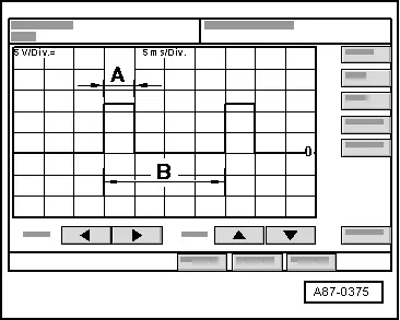
This image appears on oscilloscope screen (for example, on the Vehicle Diagnostic Tester) when the following conditions are met.
- Ignition switched on (positive at contact "3" and ground at contact "1" on High Pressure Sensor -G65- present)
- Oscilloscope setting: 5 V/div. DC (5 V per unit DC) 5 ms/div. (5 milliseconds per unit)
- Measuring cable (signal wire) connected to contact "2" on High Pressure Sensor -G65-.
- Measuring cable (shielding) connected to contact "1" (ground on High Pressure Sensor -G65-).
 Note
Note
- The illustration shows the signal, which is sent when the refrigerant circuit pressure is approximately 7 bar (101.52 psi). This conforms to a approximate 25% duty cycle. With compressor not engaged, an ambient temperature of 30 ºC (86 ºF) and properly filled refrigerant circuit.
- The impulse width -A- depends on the pressure in the refrigerant circuit (if pressure increases, area -A- gets wider).
- The signal distance -B- is always 20 milliseconds. This corresponds to frequency of 50 Hertz.
- The duty cycle is determined by the ratio of impulse width -A- and signal distance -B-.
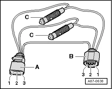
- For example, use the measuring cables from the Connector Test Set -VAG1594D- or an adapter cable for this test. To do this, for example, use one connector each -A- and -B- (part number -1J0 973 703- and -1J0 973 803- and related connector terminals; refer to the Parts Catalog), two standard sockets for banana connectors -C- and three wires with 0.5 mm 2 diameter.
READ NEXT:
 Safety Precautions
Handling Refrigerant Safety Precautions
The assemblies and piping system of the air conditioner are
filled with the following refrigerant:
1.1.1.2 Tetrafluorethane (CF3-CH2F
or CH2F-CF3)
Curren
Clean Working Conditions
Even slight contamination can lead to defects. Therefore
observe the following rules for cleanliness when working on the
A/C system:
Immediately seal the open lines and connections with clean
SEE MORE:
New tires or wheels
Audi recommends having all work
on tires or wheels performed by
an authorized Audi dealer or authorized
Audi Service Facility.
These facilities have the proper
knowledge and are equipped with
the required tools and replacement
parts.
New tires do not yet have the
optimal gripping properties.
Dr
Center Console Rear Trim, Removing and Installing
Special tools and workshop equipment
required
Wedge Set -T10383-
Removing
- Move the front seats all the way forward.
Vehicles with a Center Armrest:
- Vehicles with vents: remove the rear vent. Refer to
→ Chapter "Rear Vents, Removing and Installing".
- Equipment
