Audi Q3: Connector Assignments, Ready4Nav 7Q4, Navigation Packet 7T2
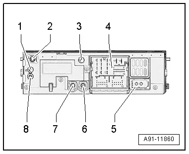
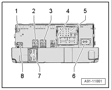
Information Electronics Control Module 1 -J794-
1 - Connector AM/FM1 from the Antenna Amplifier -R24- (Radio Antenna 2 -R93-)
2 - DAB connection from Antenna Amplifier 4 -R113-, Digital Radio Antenna -R183-
3 - GPS connection from the Roof Antenna -R216-
4 - Connection block with four multi-pin connectors
5 - MOST Bus
6 - 4-Pin Connector -T4ap- to the External Audio Source Connection -R199-/Internet Access Control Module -J666-, only with MOST
7 - 4-Pin Connector -T4d- to the Front Information Display Control Head -J685-
8 - Connection FM2 from Antenna Amplifier 3 -R112-, Antenna -R11-
Only North America and QV8
1 - Connector AM/FM1 from the Antenna Amplifier -R24- (Radio Antenna 2 -R93-)
2 - SAT connection from Roof Antenna -R216-, Satellite Antenna -R170-
3 - GPS connection from the Roof Antenna -R216-
4 - Connection block with four multi-pin connectors
5 - MOST Bus
6 - 4-Pin Connector -T4ap- to the External Audio Source Connection -R199-/Internet Access Control Module -J666-, only with MOST
7 - 4-Pin Connector -T4d- to the Front Information Display Control Head -J685-
8 - Connection FM2 from Antenna Amplifier 3 -R112-, Antenna -R11-
 Note
Note
Unlisted connector terminals are not assigned.
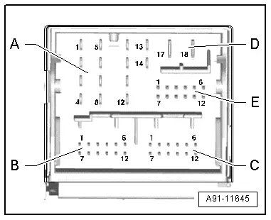
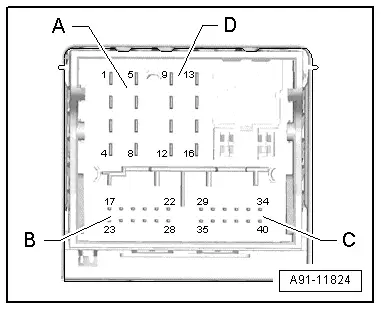
4 - Connection Block With Four Multi-Pin Connectors
A - 8-Pin Connector -T8ag-
1 - Right rear speaker (+)
2 - Right front speaker (+)
3 - Left front speaker (+)
4 - Left rear speaker (+)
5 - Right rear speaker (-)
6 - Right front speaker (-)
7 - Left front speaker (-)
8 - Left rear speaker (-)

B - 12-Pin Connector -T12x-
4 - Microphone input (+) from Microphone Unit In Front Roof Module -R164-, Telephone Microphone -R38-, only with MOST
5 - CVBS cable (-) for the Rearview Camera System Control Module -J772-
6 - DIAG signal from Telephone Baseplate -R126-
11 - CVBS cable (+) for the Rearview Camera System Control Module -J772-
12 - Microphone input (-) from Microphone Unit In Front Roof Module -R164-, Telephone Microphone -R38-, only with MOST)

C - 12-Pin Connector -T12y-
All pins are connected to the External Audio Source Connection -R199-.
1 - LF-In Ground
2 - Right LF-In
3 - USB, +5 V. not on the Internet Access Control Module -J666-, UE2
4 - USB, Ground
5 - iPod, ACC Power
6 - Detect, not on the Internet Access Control Module -J666-, UE2
7 - Left LF-In
8 - LF-In ground shielding
9 - CVBS cable (+)
10 - CVBS cable (-)
11 - iPod data
12 - iPod data

Following pins are also still connected with the Internet Access Control Module -J666-, UE2.
3 - USB, +5 V
4 - USB, Ground
6 - Detect
D - 8-Pin Connector -T8j-
9 - Subwoofer -R211-
10 - Center Speaker -R208-
13 - Subwoofer -R211-
14 - Center Speaker -R208-
17 - Terminal 31
18 - Terminal 30

E - 12-Pin Connector -T12w-
7 - Ring-break Diagnostic Cable
12 - Switch-on signal to Telephone Baseplate -R126-/Cellular Telephone Amplifier -R86-
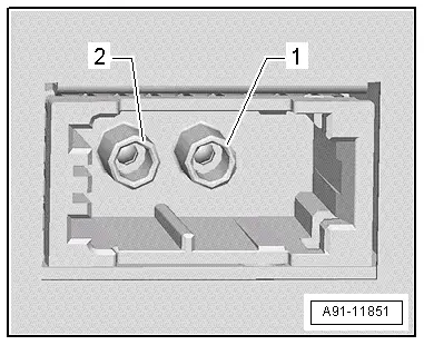
5 - MOST bus
1 - Input
2 - Output
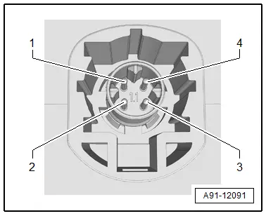
6 - 4-Pin Connector -T4ap-
All pins are connected with the External Audio Source Connection -R199-/Internet Access Control Module -J666-.
1 - D (+)
2 - iPod recognized
3 - D (-)
4 - Ground
7 - 4-Pin Connector -T4d-
All pins are connected to the Front Information Display Control Head -J685-.
1 - LVDS (-)
2 - LIN
3 - LVDS (+)
4 - Ground

Connector Assignment, MMI Navigation Plus, 7T6
Information Electronics Control Module 1 -J794-
1 - GSM connection from Roof Antenna -R216-
2 - 4-Pin Connector -T4u- to the External Audio Source Connection -R199-/Internet Access Control Module -J666-
3 - 4-Pin Connector -T4al- to the Front Information Display Control Head -J685-
4 - Not Assigned
5 - Connection block with four multi-pin connectors
6 - MOST Bus
7 - 20-Pin Connector -T20k- to the Information Electronics Control Module 1 -J794-
8 - GPS connection from the Roof Antenna -R216-
 Note
Note
Unlisted connector terminals are not assigned.
2 - 4-Pin Connector -T4u-
All pins are connected with the External Audio Source Connection -R199-/Internet Access Control Module -J666-.
1 - D (+)
2 - iPod recognized
3 - D (-)
4 - Ground

3 - 4-Pin Connector -T4al-
All pins are connected to the Front Information Display Control Head -J685-.
1 - LVDS (-)
2 - LIN
3 - LVDS (+)
4 - Ground

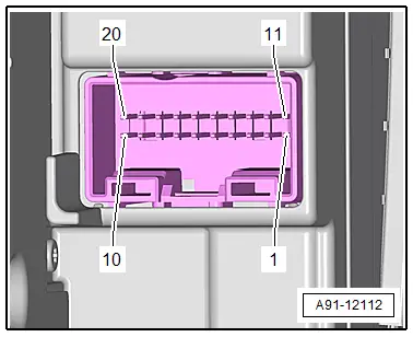
5 - Connection Block with Four Multi-Pin Connectors
A - 8-Pin Connector -T8ah-
1 - LF mute wire from preliminary setup for cell phone preparation
2 - Power supply to the Information Electronics Control Module 1 -J794-, 20-Pin Connector -T20k-
3 - Wake Up to the Information Electronics Control Module 1 -J794-, 20-Pin Connector -T20k-
4 - Not Assigned
5 - Switch-on signal for the Cellular Telephone Amplifier -R86-
6 - Res MU to the Information Electronics Control Module 1 -J794-, 20-Pin Connector -T20k-
7 - Ring-break Diagnostic Cable

B - 12-Pin Connector -T12x-
20 - VICS data wire for the Chip Card Reader Control Module -J676-, only Japan
21 - CVBS cable (-) for the Rearview Camera System Control Module -J772-
22 - ETC data for the Chip Card Reader Control Module -J676-, only Japan
24 - Microphone input (+) from Microphone Unit In Front Roof Module -R164-, Telephone Microphone -R38-
25 - Microphone input (-) from Microphone Unit In Front Roof Module -R164-, Telephone Microphone -R38-
26 - VICS data wire to the Chip Card Reader Control Module -J676-, only Japan
27 - CVBS cable (+) for the Rearview Camera System Control Module -J772-
28 - ETC data to the Chip Card Reader Control Module -J676-, only Japan
C - 12-Pin Connector -T12k-
All pins are connected to the External Audio Source Connection -R199-.
29 - LF-In Ground
30 - Right LF-In
31 - USB, +5 V. not on the Internet Access Control Module -J666-, UE2
32 - USB, Ground
33 - iPod, ACC Power
34 - Detect, not on the Internet Access Control Module -J666-, UE2
35 - Left LF-In
36 - LF-In ground shielding
37 - CVBS cable (+)
38 - CVBS cable (-)
39 - iPod data
40 - iPod data

Following pins are also still connected with the Internet Access Control Module -J666-, UE2.
31 - USB, +5 V
32 - USB, Ground
34 - Detect
D - 8-Pin Connector -T8ao-
10 - Data from Information Electronics Control Module 1 -J794-, 20-Pin Connector -T20k-
11 - Data to Information Electronics Control Module 1 -J794-, 20-Pin Connector -T20k-
12 - Terminal 31
13 - DIAG signal from Telephone Baseplate -R126-
14 - Res BT from Information Electronics Control Module 1 -J794-, 20-Pin Connector -T20k-
15 - Terminal 30
16 - Ground to Information Electronics Control Module 1 -J794-, 20-Pin Connector -T20k-

6 - MOST bus
1 - Output
2 - Input

7 - 20-Pin Connector -T20k-
6 - Wake UP to the Information Electronics Control Module 1 -J794-
7 - Power supply from the Information Electronics Control Module 1 -J794-
8 - Ground to the Information Electronics Control Module 1 -J794-
13 - Res MU from the Information Electronics Control Module 1 -J794-
14 - Res MU to the Information Electronics Control Module 1 -J794-
15 - Information Electronics Control Module 1 -J794- data
16 - Data from Information Electronics Control Module 1 -J794-
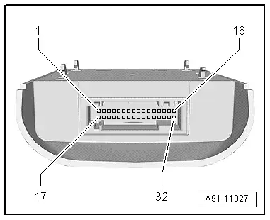
Chip Card Reader Control Module -J676-, Connector Assignment
 Note
Note
Unlisted connector terminals are not assigned.
32-Pin Connector -T32ja-
1-16 - To the Traffic Data Antenna -R173-
17 - VICS data wire to the Information Electronics Control Module 1 -J794-
19 - VICS data wire to the Information Electronics Control Module 1 -J794-
21 - Switch-on signal to the Information Electronics Control Module 1 -J794-
22 - Terminal 30
23 - ETC data to the Information Electronics Control Module 1 -J794-
25 - ETC data from the Information Electronics Control Module 1 -J794-
28 - Terminal 31
READ NEXT:
 Overview - Rearview Camera System
The rear view camera system assists the driver when driving
in reverse by providing the driver with an image of the traffic
situation behind the vehicle via the Front Information Display
Control
Rearview Camera -R189-, Removing and Installing
The Rearview Camera -R189- is inside the rear lid handle
button. It permanently attached to the button.
If the Rearview Camera -R189- must be replaced, then the
handle button must also be replace
SEE MORE:
Laws and Regulations
General Information
Note
The laws and regulations listed below are applicable in
Germany. Different or additional laws and regulations may apply
in other countries.
The effects of climate change can be seen worldwide.
Protecting the climate is one of the most important
responsibi
Door Windows
Overview - Front Door Window
1 - Door Window
Removing and installing. Refer to
→ Chapter "Front Door Window, Removing and Installing".
2 - Door
3 - Driver Window Regulator Motor -V147-
4 - Speaker
Removing. Refer to
→ Communic
