Audi Q3: Rearview Camera -R189-, Removing and Installing
The Rearview Camera -R189- is inside the rear lid handle button. It permanently attached to the button.
If the Rearview Camera -R189- must be replaced, then the handle button must also be replaced.
Removing
- Turn off the ignition and all electrical equipment and remove the ignition key.
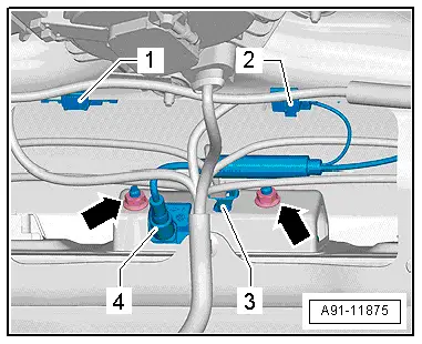
The Rearview Camera -R189- has a trailing cable. The vehicle wiring harness couplings are located in the rear lid.
- Remove the lower rear lid trim panel. Refer to → Body Interior; Rep. Gr.70; Luggage Compartment Trim Panel; Rear Lid Lower Trim Panel, Removing and Installing.
- Release and disconnect the connectors -12 and 3- in the rear lid.
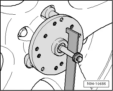
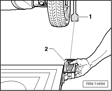
The Rearview Camera -R189--4- is firmly attached to the handle button.
- Remove the nuts -arrows-.
- Pull the handle button -3- with the Rearview Camera -R189- out of the retainer in the rear lid.
Installing
- Install in reverse order of removal.
- Close the rear lid.
- Perform the calibration. Refer to → Chapter "Rearview Camera System, Calibrating".
Rearview Camera System Control Module -J772-, Removing and Installing
The Rearview Camera System Control Module -J772--1- is located behind the left luggage compartment trim panel.
 Note
Note
If replacing the control module, select the "Replace control module" function for the corresponding control module on the Vehicle Diagnostic Tester.
Removing
- Turn off the ignition and all electrical equipment and remove the ignition key.
- Remove the cover in the left of the luggage compartment and fold the insolation to the side.
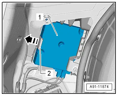
The Rearview Camera System Control Module -J772--1- is only clipped into the bracket.
- Press the catch -2- in direction of -arrow- and remove the Rearview Camera System Control Module -J772--1- from the bracket.
- Release and disconnect the connectors from the Rearview Camera System Control Module -J772--1-.
Installing
- Install in reverse order of removal.
- Perform the calibration. Refer to → Chapter "Rearview Camera System, Calibrating".

Rearview Camera System, Calibrating
Calibration Unit -VAS6350A-, Installing and Aligning
After performing service work on the vehicle, it may be necessary to re-calibrate the rearview camera system. In detail, this is the case after:
- Rearview Camera -R189- removal and installation
- Replacing Rearview Camera System Control Module -J772-
- Collision repairs on rear lid
- Changes to the axle alignment on the rear axle
Calibration Requirements
- The camera lens must be clean.
- The vehicle must be standing on a firm and level surface.
- There must be enough clearance around the vehicle (at least 2 meters (2.1 yards) ).
- The parking brake must be set.
- The steering wheel must be in the 0 position and the wheels must be straight.
- All doors and the rear lid must be closed.
- No one should be in the vehicle.
- The vehicle must not be loaded (curb weight).
- Connect the battery charger.
- Ignition switched on.
Special tools and workshop equipment required
- Calibration Unit -VAS6350A-
- Vehicle Diagnostic Tester
The Calibration Unit -VAS6350A- consists of the following parts:
- Calibration Tool - Wheel Center Mountings -VAS6350/1-
- Calibration Tool - Spacing Laser -VAS6350/2-
- Calibration Tool - Linear Laser -VAS6350/3-
Installed Calibration Unit -VAS6350A- Overview
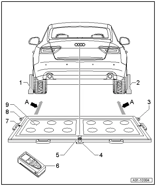
1 - Calibration Tool - Wheel Center Mountings -VAS6350/1-
2 - Calibration Tool - Wheel Center Mountings -VAS6350/1-
3 - Right Angle Bracket
- Calibration Tool - Spacing Laser -VAS6350/2- mount
4 - Plastic Foot
- Three on underside of the calibration board
- Adjustable for aligning horizontal position of the calibration board
5 - Calibration Tool - Linear Laser -VAS6350/3-
- On the calibration board
- Switching on and off. Refer to the Owner's Manual.
6 - Calibration Tool - Spacing Laser -VAS6350/2-
- On the calibration board
- Refer to the Owner's Manual for notes on the operation.
7 - Level
- On the calibration board
- For checking the horizontal position
8 - Left Angle Bracket
- Calibration Tool - Spacing Laser -VAS6350/2- mount
9 - Calibration Board
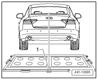
- Between the mounts on the calibration board and the Calibration Tool - Wheel Center Mountings -VAS6350/1--dimension A- 1.47 m through 1.90 m.
Calibration Board Orientation
- Position the calibration platform behind the vehicle at a distance of 1.47 m to 1.90 m to the rear wheels, see -dimension A- in the illustration.
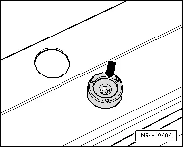
- Bring the Calibration Unit -VAS6350A- into a horizontal position.
- Twist the plastic feet under the calibration board so that the air bubble in the level is located exactly in the center of the indicator -arrow-.
 WARNING
Make sure light does not reflect off the calibration board.
Reflections affect the Rearview Camera -R189- and may make it impossible to perform the calibration.
- Switch on the Calibration Tool - Linear Laser -VAS6350/3--1- on the calibration board and adjust the entire Calibration Unit -VAS6350A- so that the laser beam hits the center of vehicle rear above the Audi rings.
- Make sure the Audi rings are centered on the rear. Correct the laser beam accordingly.
Continue calibrating the Rearview Camera -R189-. Refer to → Chapter "Rearview Camera -R189-, Calibrating".
Rearview Camera -R189-, Calibrating
- Establish the requirements.
- Connect the Vehicle Diagnostic Tester.
Calibration Tool - Wheel Center Mountings -VAS6350/1- installing:
- Check the dimension of the holes.
- Equip the Calibration Tool - Wheel Center Mountings -VAS6350/1- appropriately. Use spacer pieces.
- To do so, secure three wheel bolt adapters in the hole circle to each Calibration Tool - Wheel Center Mountings -VAS6350/1-.
- Place the paddle on both Calibration Tool - Wheel Center Mountings -VAS6350/1- and secure them using a clamping screw.
- Place the Calibration Tool - Wheel Center Mountings -VAS6350/1- onto the wheel bolts on the rear wheels.
The Calibration Tool - Wheel Center Mountings -VAS6350/1- are positioned by the "O-rings" in the adapters and secured.
 Note
Note
Attach the Calibration Tool - Wheel Center Mountings -VAS6350/1- onto the wheels so that any installed "anti-theft" wheel mounting bolts are not connected to the Calibration Tool - Wheel Center Mountings -VAS6350/1-.
- Adjust the paddles with aid of lock bolts so that they move freely just above the floor. Check the paddles for ease of movement.
- Install and align the Calibration Unit -VAS6350A-. Refer to → Chapter "Calibration Unit -VAS6350A-, Installing and Aligning".
Distance measurement:
- Switch on the Calibration Tool - Spacing Laser -VAS6350/2-.
The Following Display Appears
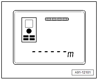
The display shows how to stop the Calibration Tool - Spacing Laser -VAS6350/2-. Press the corresponding button.
1 - Attach with front edge
2 - Attach with rear edge
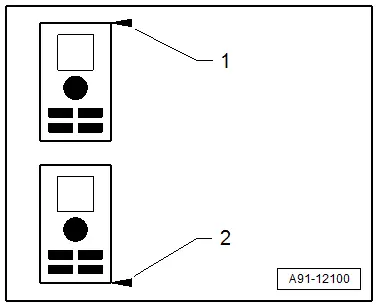
- Hold the Calibration Tool - Spacing Laser -VAS6350/2--2- flush in the bracket on one side of the calibration board (attach with rear edge). The Calibration Tool - Spacing Laser -VAS6350/2--2- must sit securely on the bracket.
- Press the measuring button briefly.
The laser switches on.
- Make sure that laser beam from Calibration Tool - Spacing Laser -VAS6350/2--2- hits lower, enlarged part of paddle -1-.
If this is not the case, the paddles must be corrected accordingly via clamping screws on the Calibration Tool - Wheel Center Mountings -VAS6350/1-.
- Use one hand to secure the Calibration Tool - Spacing Laser -VAS6350/2- in the bracket on the Calibration Tool -VAS6350- while the laser beam is visible on the paddle.
- Then press the measurement button for the distance measurement briefly.
- Write down the value.
- Repeat this measurement on the other side of the Calibration Tool -VAS6350- in the same way for the rear wheel.
The distance value must be the same on both sides.
If values are not identical:
- Align the Calibration Unit -VAS6350A- long enough so that both sides are identical.
Pay attention when aligning the Calibration Tool -VAS6350-, that the Calibration Tool - Linear Laser -VAS6350/3- from the Calibration Tool -VAS6350- strikes the center of the Audi rings and the indicator of the level remains centered. Adjust if necessary.
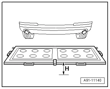
Measurement -dimension H-:
- Measure the height of the Calibration Tool -VAS6350-, -dimension H- (top edge platform - floor).
Make sure the Calibration Tool - Spacing Laser -VAS6350/2- is adjusted correctly (attach with front edge).
The display shows how to stop the Calibration Tool - Spacing Laser -VAS6350/2-. Press the corresponding button.
1 - Attach with front edge
2 - Attach with rear edge
 v
v
Enter the height and distance dimensions into the Vehicle Diagnostic Tester in "millimeters".
Calibrating
The Vehicle Diagnostic Tester is connected.
- Select the Diagnostic mode and start the diagnosis.
- Select the Test plan tab.
- Press the Select individual tests button and select the following one after the other:
- Body
- Electrical Equipment
- 01 - OBD-capable systems
- 6C - rearview camera system/J772
- 6C - Rearview camera system control module, functions
- 6C - Calibration, (Repair Group 91)
From here, the Vehicle Diagnostic Tester advances the calibration procedure forward.
 WARNING
Make sure light does not reflect off the calibration board.
Reflections affect the Rearview Camera -R189- and may make it impossible to perform the calibration.
Connector Assignments
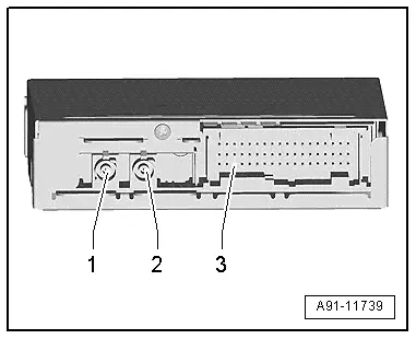
Rearview Camera System Control Module -J772-
1 - CVBS input from the Rearview Camera -R189-
2 - CVBS output to the Information Electronics Control Module 1 -J794-
3 - 54-Pin Connector -T54a-
 Note
Note
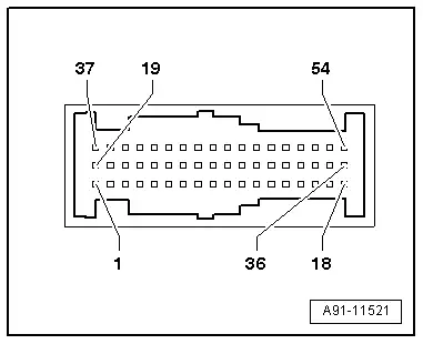
Unlisted connector terminals are not assigned.
3 - 54-Pin Connector -T54a-
39 - Convenience CAN bus low
40 - Convenience CAN bus high
43 - Terminal 30
44 - Terminal 31
47 - Terminal 31 to the Rearview Camera -R189-
48 - Rearview Camera -R189- power supply
READ NEXT:
 Multifunction Steering Wheel
Overview - Multifunction Steering Wheel
Buttons are integrated in the steering wheel for easier
operation of Infotainment, telephone and the navigation system.
On vehicles with Tiptronic, rock
Connection for External Multimedia Devices
Overview - External Multimedia Devices
There are several External Audio Source Connection -R199-
versions:
AMI (Audi Music Interface), MOST, UF7
The interface -1- is located in
the center conso
Mobile Online Services
Overview - Mobile Online Services
The Internet Access Control Module -J666- (Audi music
interface online, UE2) expands the External Audio Source
Connection -R199- (AMI) using the following functiSEE MORE:
Wheel Bearing Housing Bonded Rubber Bushing, Replacing
Wheel Bearing Housing Bonded Rubber Bushing, Replacing, FWD Vehicles
Special tools and workshop equipment
required
Bearing Installer - Control Arm -3346-
Bearing Installer - Carrier Bearing -3350-
Fitting Sleeve -3378-
Torque Adapter -3390-
Torque Wrench 1332 40-200Nm -VAG1332-
Rem
Vehicle Diagnosis, Testing and Information Systems
WARNING
During road tests using a vehicle diagnostic and
information system, there is the hazard of extreme to
lethal injuries!
If vehicle diagnostic and information system is
deposited in the action area of an airbag during a road
test, here is the hazard of extreme to letha