Audi Q3: Trailing Arm, Servicing
Trailing Arm, Servicing, FWD Vehicles
Special tools and workshop equipment required
- Press Plate -VW401-
- Press Plate -VW402-
- Front Subframe Mount Kit -3372-
- Hydraulic Press - Bushing Assembly Tool Kit -T10230-
Pressing out the bonded rubber bushing
- Remove trailing arm with mounting bracket. Refer to → Chapter "Trailing Arm with Mounting Bracket, Removing and Installing, FWD Vehicles".
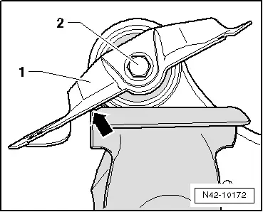
- Clamp the trailing arm in the vise so that the mounting bracket -1- contacts the vise -arrow-.
- Remove the bolt -2-.

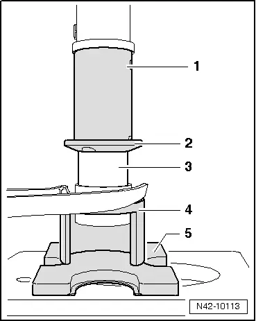
- Install tools as shown in the illustration.
1 - Hydraulic Press - Bushing Assembly Tool Kit-Pipe -T10230/3-
2 - Hydraulic Press - Bushing Assembly Tool Kit-Press Piece -T10230/10-
3 - Front Subframe Mount Kit -3372-
4 - Press Plate -VW401-
5 - Press Plate -VW402-
- Press out the bonded rubber mount.

Installing the bonded rubber bushing
- Place the trailing arm on a flat surface.
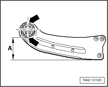
- Position the trailing arm so that the dimension -A- 113 mm is reached.
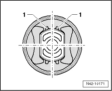
- In this position, apply a vertical line (marking on the upper and lower edge of the bushing) that is centered with the trailing arm bushing -arrows-.

- Position the bonded rubber bushing on the trailing arm so that the marked line is between the raised sections -1-.
 Note
Note
Always make sure that the bonded rubber bushing is in the correct installation position to the trailing arm bushing.

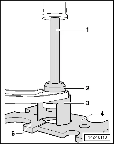
- Install tools as shown in the illustration.
1 - Hydraulic Press - Bushing Assembly Tool Kit - Tube -T10230/5-
2 - Hydraulic Press - Bushing Assembly Tool Kit-Thrust Plate -T10230/12-, the chamfer must face the bonded rubber bushing
3 - Bonded rubber bushing
4 - Front Subframe Mount Kit -3372-
5 - Press Plate -VW402-
- Press in bonded rubber bushing flush.
- Install the mounting bracket on trailing arm.
- Install trailing arm with mounting bracket. Refer to → Chapter "Trailing Arm with Mounting Bracket, Removing and Installing, FWD Vehicles".
Trailing Arm, Servicing, AWD Vehicles
Special tools and workshop equipment required
- Press Plate -VW401-
- Press Plate -VW402-
- Front Subframe Mount Kit -3372-
- Hydraulic Press - Bushing Assembly Tool Kit -T10230-
Pressing out the bonded rubber bushing
- Remove trailing arm with mounting bracket. Refer to → Chapter "Trailing Arm with Mounting Bracket, Removing and Installing, FWD Vehicles".
- Clamp the trailing arm into vise so that the mounting bracket -1- makes contact at vise -arrow-.
- Remove the bolt -2-.
- Install tools as shown in the illustration.
1 - Hydraulic Press - Bushing Assembly Tool Kit-Pipe -T10230/3-
2 - Hydraulic Press - Bushing Assembly Tool Kit-Press Piece -T10230/10-
3 - Front Subframe Mount Kit -3372-
4 - Press Plate -VW401-
5 - Press Plate -VW402-
- Press out the bonded rubber mount.

Installing the bonded rubber bushing
- Place the trailing arm on a flat surface.
- Position the trailing arm so that the dimension -A- 113 mm is reached.
- In this position, apply a vertical line (marking on the upper and lower edge of the bushing) that is centered with the trailing arm bushing -arrows-.
- Position the bonded rubber bushing on the trailing arm so that the marked line is between the raised sections -1-.
 Note
Note
Always make sure that the bonded rubber bushing is in the correct installation position to the trailing arm bushing.
- Install tools as shown in the illustration.
1 - Hydraulic Press - Bushing Assembly Tool Kit - Tube -T10230/5-
2 - Hydraulic Press - Bushing Assembly Tool Kit-Thrust Plate -T10230/12-, the chamfer must face the bonded rubber bushing
3 - Bonded rubber bushing
4 - Front Subframe Mount Kit -3372-
5 - Press Plate -VW402-

- Press bonded rubber bushing in flush.
- Install the mounting bracket on trailing arm.
- Install trailing arm with mounting bracket. Refer to → Chapter "Trailing Arm with Mounting Bracket, Removing and Installing, FWD Vehicles".
READ NEXT:
 Overview - Drive Axle
Overview - Drive Axle, Drive Axle with 100 mm Inner CV Joint
Note
Grease joint again when replacing protective joint boot.
1 - Outer CV Joint
Replace only as complete unit
Drive Axle, Removing and Installing
Removing
- Measure dimension from center of wheel to lower edge of
wheel housing. Refer to
→ Chapter "Wheel Bearing in Curb Weight, Lifting Vehicles with
Coil Spring".
- Loose
Drive Axle, Disassembling and Assembling
Drive Axle, Disassembling and Assembling, Drive Axle with 100 mm Inner CV
Joint
Special tools and workshop equipment
required
Tripod Joint Tool -T10065-
Torque Wrench 1331 5-50Nm -VAG1331-
SEE MORE:
General information
Safety precautions
WARNING
As the driver, you are always completely responsible
for all driving tasks. The assist
systems cannot replace the driver's attention.
Give your full attention to driving the
vehicle, and be ready to intervene in the
traffic situation at all times.
Activate the ass
Map update
Introduction
Applies to: vehicles with navigation system
You can update the map data in the MMI with a
map update. The functions depend on the country
and vehicle equipment.
Map update through online map update.
Import a map update from the USB connection
to your MMI.
Online map update
Applies 