Audi Q3: Backrest Adjuster, Removing and Installing
Backrest Adjustment Hand Wheel, Removing and Installing
 Note
Note
Only the hand wheel for the backrest adjustment wheel can be removed and installed.
Special tools and workshop equipment required
- Assembly Tool -3399-
Removing
- Move the front seat all the way forward/up.
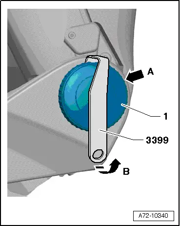
- Turn the backrest adjustment wheel -1- until one catch is visible from behind -arrow A-. Use a flashlight if necessary.
- Attach the Assembly Tool -3399- to the catch and pry off the hand wheel -arrow B-.
- Turn the backrest adjustment wheel 120º farther and repeat the process.
- Remove the backrest adjustment hand wheel.
Installing
Install in reverse order of removal.
Installation notes, for example tightening specifications, replacing components. Refer to → Chapter "Overview - Seat Pan, Sill Panel/Tunnel Side Seat Side Trim on Manual Front Seat".
Driver/Front Passenger Backrest Adjustment Motor -V45-/-V46-, Removing and Installing
Special tools and workshop equipment required
- Pop Rivet Pliers -VAG1753B-
- Drill
- Protective eyewear
- Locking compound. Refer to the Parts Catalog.
Removing
 WARNING
- Follow all safety precautions when working with pyrotechnic components. Refer to → Chapter "Pyrotechnic Components Safety Precautions".
- Before handling airbag units (for example, disconnecting the connector), the person handling it must "discharge static electricity". This can be done by touching the door striker, for example.
- Remove the front seat. Refer to → Chapter "Front Seat, Removing and Installing".
- Fasten the front seat on the Engine/Transmission Holder - Seat Repair Fixture -VAS6136-. Refer to → Chapter "Front Seat, Mounting on Fixture for Seat Repair".
- Remove the Seat side trim on the tunnel side. Refer to → Chapter "Seat Side Trim on the Tunnel Side, Removing and Installing".
- Remove the seat side sill panel trim. Refer to → Chapter "Seat Side Trim on Sill Panel Side, Removing and Installing, Power Front Seat".
- Remove the backrest cover. Refer to → Chapter "Backrest Cover, Removing and Installing".
- Mark the angle adjustment of the left and right backrest mounting brackets on the front seat as follows:
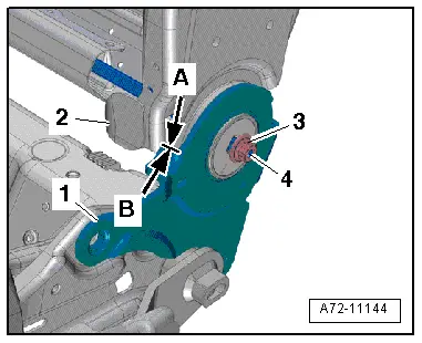
- Apply mark -arrow B- to the backrest frame with a waterproof marker -2- directly at the front edge -arrow A- of the hinge -1-.
- Remove nut -3- on the adjustment shaft -4-.
- Remove the cover from the backrest near the backrest hinge. Refer to → Chapter "Backrest Cover and Cushion, Removing and Installing".
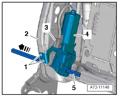
- Remove adjustment shaft -5- from the backrest frame -2--arrow-.
- Disconnect harness connector -3- at the backrest adjustment motor.
 Note
Note
Lay plastic film between the seat cover and the backrest frame to protect against metal shavings.
 WARNING
Danger of eye injury.
Wear protective eyewear.
- Drill out rivets -1-, remove backrest adjustment motor -4- with bracket.
Installing
- Check the position of the backrest frame -2- and the anchor -1- on the left and right side.
- The left and right backrest frames must be in the position marked before removal -A and B arrows-.
- If the left and right backrest frames are not in the position marked before removal, correct their position accordingly.

- Set backrest adjustment motor -3- with bracket in place.
- It must still be possible to move the backrest adjustment motor.
- First slide the adjustment shaft through the hinge (tunnel side) as far as the mount -4- in the backrest adjustment motor.
- Check whether the profile of the inserted adjustment shaft and mount in the backrest adjustment motor align.
- If the shaft adjustment profile and the mount in the backrest adjustment motor do not align, connect an external 12-volt power source to the backrest adjustment motor -3- and turn mount until the profiles of the adjustment shaft and mount are aligned
- Slide the adjustment shaft -5- through the mount in the backrest adjustment motor as far as the stop (sill panel trim) -arrow-.
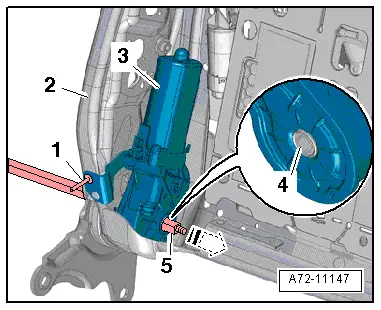
- Install the new nut -3- on the adjustment shaft -4- and tighten it.

- Rivet bracket with motor to the backrest frame -2--1-.
Installation is performed in reverse order of removal, while noting the following:
 WARNING
- Follow all safety precautions when working with pyrotechnic components. Refer to → Chapter "Pyrotechnic Components Safety Precautions".
- Before handling pyrotechnic components (for example, connecting the connector), the person handling it must "discharge static electricity". This can be done by touching the door striker, for example.
- Observe all measures when installing the front seat. Refer to → Chapter "Front Seat, Removing and Installing".
Installation notes, for example tightening specifications, replacing components. Refer to → Chapter "Overview - Front Backrest, Backrest Adjustment Motor".

READ NEXT:
 Front Backrest, Removing and Installing
Backrest Cover, Removing and Installing
Removing
WARNING
Danger of being injured by burrs on the backrest
cover.
Wear protective gloves.
- Reach behind the backrest cover -1-
a
Headrest, Removing and Installing
Note
The headrests can be removed with the front seats installed.
Removing
- Move the front seat forward into the lowest position and
tilt backrests approximately 45º.
No
Modular Wiring Routing with Corrugated Tube
Opening the corrugated tube and removing the individual wire
WARNING
Follow all safety precautions when working with
pyrotechnic components. Refer to
→ Chapter "Pyrotechnic C
SEE MORE:
Audi drive select
Introduction
Applies to: vehicles with Audi drive select
Drive select makes it possible to experience different
types of vehicle characteristics in one vehicle.
With different driving modes, the driver can
switch the setting, for example from sporty to
comfortable. This allows you to adjust the set
Cooling Output, Checking, Automatic Climate Control System
Procedure
The requirements for testing the cooling capacity are
fulfilled. Refer to
→ Chapter "A/C Cooling Output, Testing Requirements".
- Measure the ambient temperature (must be warmer than 15 ºC
(59 ºF) ).
- Close the doors, the engine hood, the windows, the sunr
