Audi Q3: Cooling Output, Checking, Automatic Climate Control System
Procedure
- The requirements for testing the cooling capacity are fulfilled. Refer to → Chapter "A/C Cooling Output, Testing Requirements".
- Measure the ambient temperature (must be warmer than 15 ºC (59 ºF) ).
- Close the doors, the engine hood, the windows, the sunroof and the rear lid.
- Open all instrument panel vents and, if present, the vents in the rear center console.
- Start the engine.
- Switch off the Air Conditioning (A/C) compressor. The indicator lamp in the AC or A/C button -1- does not illuminate.
- "Read measured values", A/C system using the Vehicle Diagnostic Tester in the "Guided Fault Finding" function.
Checking
- Read the actuation of the A/C Compressor Regulator Valve -N280-.
- The activation of the A/C compressor is switched off and 0 A (amp) is displayed.
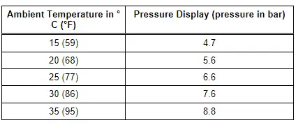
- The refrigerant circuit pressure at the measured ambient temperature is same as or greater than the value in the table.

 Note
Note
- At absolute pressure, 0 bar corresponds to absolute vacuum. Normal ambient pressure equals approximately 1.0 bar (14.5 psi) absolute pressure and 0 bar pressure. On the scales of most pressure gauges, 0 bar pressure corresponds to an absolute pressure of one bar (can be seen from -1 mark below 0).
- Depending on the version of the Climatronic Control Module -J255-, only integer values may be displayed as measured values. If the measured pressure is between two values, the display alternates between the two values.
- Pressure in refrigerant circuit is governed by ambient temperature. On account of heat given off by components (for example, the radiator), pressure displayed with warm engine will be slightly higher than that given for the respective ambient temperature.
If pressure displayed is below that indicated in table:
- Check the signal of the High Pressure Sensor -G65-. Refer to Vehicle Diagnostic Tester in the "Guided Fault Finding" and → Chapter "High Pressure Sensor -G65-, Checking Pressure Signal".
- If no fault can be determined at the High Pressure Sensor -G65-, then there is not enough refrigerant in the circuit. Bring the vehicle to a workshop that has the necessary tools and in which the work can be performed accordingly by qualified personnel. Refer to → Refrigerant R134a, Servicing; Rep. Gr.87; A/C System, General Information (Refrigerant R134a, Servicing; A/C System, General Information).
If the Refrigerant Circuit Pressure Is OK.
Adjust the following settings on the Climatronic Control Module -J255- control head:
- "Auto" mode - the indicator lamp in the AUTO button -10- illuminates.
- Temperature preset "cold" via the knobs -2 and 8- - "LO" for the driver and front passenger side in the display -6- on the Climatronic Control Module -J255-.
- The A/C compressor is on - the indicator lamp in the AC or A/C button -1- illuminates.
- "Read measured values", A/C system using the Vehicle Diagnostic Tester in the "Guided Fault Finding" function.
- Check the display in the display fields:
- The A/C compressor is switched on, the current greater than 0.3 A is displayed (the current flows via the A/C Compressor Regulator Valve -N280-).
- The A/C compressor is switched on; a duty cycle greater than 30 % is displayed (the A/C Compressor Regulator Valve -N280- is activated).
- The displayed pressure increases above the value when the compressor is switched off.
 Note
Note
- If the displayed pressure in the displayed measured value does not change and the A/C compressor activation is OK, check once more if the A/C compressor is actually being driven and the A/C Compressor Regulator Valve -N280- is being activated. If the A/C compressor is being driven and the A/C Compressor Regulator Valve -N280- is activated, there is a malfunction in the refrigerant circuit. Bring the vehicle to a workshop that has the necessary tools and in which the work can be performed accordingly by qualified personnel. Refer to → Refrigerant R134a, Servicing; Rep. Gr.87; A/C System, General Information (Refrigerant R134a, Servicing; A/C System, General Information). If the A/C compressor control is not OK, then inform the workshop of the problem at hand.
- The Climatronic Control Module -J255- actuates the A/C Compressor Regulator Valve -N280- so that the air temperature reaches the specified value downstream of the evaporator (approximately 2 to 5 ºC (36º to 41 ºF) ).
- A value greater than 75% (0.55 A) is displayed after vehicle start, depending on measured temperature, engine RPM and electrical system voltage for the activation of A/C Compressor Regulator Valve -N280-. As soon as the temperature measured by the Evaporator Vent Temperature Sensor -G263- nears the specified value, the activation, and thus the A/C compressor output, is reduced.
- Under certain operating conditions, moisture in the refrigerant circuit can lead to ice build-up on the A/C Compressor Regulator Valve -N280- (and on the expansion valve). A/C compressor regulation is reduced by this ice build-up. The evaporator is cooled too intensely and freezes. The ice on the evaporator may cause various customer concerns. Refer to → Chapter "Ice Formation on Evaporator, Localizing Malfunction".
- If no or very little current is displayed in the measured values for the A/C Compressor Regulator Valve -N280- actuation, check the actuation of the A/C Compressor Regulator Valve -N280-. Refer to Vehicle Diagnostic Tester in the "Guided Fault Finding" function.
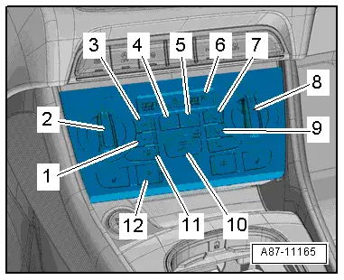
- Press the recirculation button -3- (or -12-, depending on the version) on the Climatronic Control Module -J255- control head.
- The indicator lamp for the "recirculating air mode" illuminates in the button.
- Set engine speed of 2000 rpm (start of time measurement).
- "Read measured values", A/C system using the Vehicle Diagnostic Tester in the "Guided Fault Finding" function.

- Compare the displayed measured value for the Evaporator Vent Temperature Sensor -G263- with the values in the diagram.
A - Air temperature measured by the Evaporator Vent Temperature Sensor -G263-
B - Ambient temperature
C - Permissible tolerance range
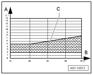
- Depending on the ambient temperature, the measured air temperature should be after 5 minutes within the shown tolerance range.
If the values required are not reached:
- Compare the measured values of the Left Vent Temperature Sensor -G150- and the Right Vent Temperature Sensor -G151- with the displayed measured value for the Evaporator Vent Temperature Sensor -G263-.
 Note
Note
The temperature of the air coming from the instrument panel vents can also be measured with a thermometer.
- If the measured value of the Evaporator Vent Temperature Sensor -G263- only slightly deviates from the measured value for the Left Vent Temperature Sensor -G150- and the Right Vent Temperature Sensor -G151-. Perform the procedure for identifying malfunctions if specified values are not reached. Refer to → Chapter "Determining Malfunction if Deviation from Specified Value".
- If the measured value of the Evaporator Vent Temperature Sensor -G263- is greater than the measured value of the Left Vent Temperature Sensor -G150- or the Right Vent Temperature Sensor -G151-, check the Evaporator Vent Temperature Sensor -G263- for proper installation (refer to → Chapter "Evaporator Vent Temperature Sensor -G263-, Removing and Installing") and perform an electrical test for this sensor. Refer to Vehicle Diagnostic Tester in the "Guided Fault Finding" function.
 Note
Note
The A/C system function is recognizable, for example, when the refrigerant pipe on the low pressure side (thick line) cools off.
If the measured value of the Evaporator Vent Temperature Sensor -G263- (and thus the A/C system cooling output) is OK and if there is no complaint, the cooling output test ends.
- If the measured value of the Evaporator Vent Temperature Sensor -G263- (and thus the A/C system cooling output) is not OK, determine the malfunction causing the deviation from specified value (the requested cooling output is not reached). Refer to → Chapter "Determining Malfunction if Deviation from Specified Value".
- If the measured value of the Evaporator Vent Temperature Sensor -G263- (and thus the A/C system cooling output) is OK and if there is a complaint that the A/C system vent temperatures are too high or differ, check the activation of the temperature doors in the A/C unit. Refer to → Chapter "Heating Output, Checking" and Vehicle Diagnostic Tester in the "Guided Fault Finding" function.
Determining Malfunction if Deviation from Specified Value
The required cooling output is not attained. Refer to → Chapter "Cooling Output, Checking, Manual Climate Control System" and → Chapter "Cooling Output, Checking, Automatic Climate Control System".
 Note
Note
This repair manual only outlines the checking procedure. Perform the detailed function test for the heating as described in the Guided Fault Finding using the Vehicle Diagnostic Tester in the "Guided Fault Finding" function.
If a target value is not reached, this can be caused by various things:
- Determine the cause. Refer to Vehicle Diagnostic Tester in the "Guided Fault Finding" function.
Possible causes for the deviation of the target value:
- Dirty radiator or Air Conditioning (A/C) system condenser.
- Retrofitted components at or in the front end.
- Fault in the activation or function of the Coolant Fan -V7-/Coolant Fan 2 -V177-.
- Fault in the coolant circuit, the coolant gets too hot.
- Fault in the activation of the A/C Compressor Regulator Valve -N280- by the A/C Control Module -J301-/Climatronic Control Module -J255-.
- Requests transmitted by other control modules to the A/C Control Module -J301-/Climatronic Control Module -J255- to switch off the A/C Compressor Regulator Valve -N280- actuation.
- Fault in the A/C Compressor Regulator Valve -N280- function.
- Fault in the refrigerant circuit or A/C compressor.
If a fault was detected in the refrigerant circuit by the "Guided Fault Finding":
- The necessary work may only be performed by qualified personnel. If this is not possible, bring the vehicle to a workshop that has the necessary tools and in which the work can be performed accordingly by qualified personnel. Refer to → Refrigerant R134a, Servicing; Rep. Gr.87; A/C System, General Information (Refrigerant R134a, Servicing; A/C System, General Information). Bring the detected problems to the attention of the workshop.
Determining Malfunction of Temperature Increase Downstream from Evaporator
The required cooling output is not attained. Refer to → Chapter "Cooling Output, Checking, Manual Climate Control System" and → Chapter "Cooling Output, Checking, Automatic Climate Control System".
 Note
Note
This repair manual only outlines the checking procedure. Perform the detailed function test for the heating as described in the Guided Fault Finding using the Vehicle Diagnostic Tester in the "Guided Fault Finding" function.
If a target value is not reached due to a temperature increase downstream from the evaporator, this can be caused by various things:
- Determine the cause. Refer to Vehicle Diagnostic Tester in the "Guided Fault Finding" function.
Possible causes for the deviation of the target value:
- Due to a fault in the activation, the temperature doors do not reach the end stops correctly in the Air Conditioning (A/C) unit.
- One or several measured values of the temperature sensors are faulty.
- Warmed up air flows by the temperature doors set in the "cold" position.
 Note
Note
This fault can be determined as follows: Clamp off both coolant hoses from the engine to the A/C heater core using, for example, the Hose Clamps - Up To 40mm -3093- and then repeat the cooling output test. If the measured values are then OK, this indicates a fault near the temperature doors.
Ice Formation on Evaporator, Localizing Malfunction
- The A/C Compressor Regulator Valve -N280- is activated by the Climatronic Control Module -J255-/A/C Control Module -J301- control head so that the temperature of the air downstream from the evaporator reaches the specified value (approximately 2 to 5 ºC (36º to 41 ºF) ).
- Depending on the measured temperature, engine RPM and electrical system voltage in Read measured values of the Climatronic Control Module -J255-/ A/C Control Module -J301- control head for the actuation of the A/C Compressor Regulator Valve -N280-, a value greater than 75% (0.55 A) is displayed after the vehicle start. Refer to Vehicle Diagnostic Tester in the "Guided Fault Finding" function. As soon as temperature measured by the Evaporator Vent Temperature Sensor -G263- approaches the specified value, actuation is cancelled and compressor output is thus reduced.
- Under certain operating conditions, moisture in the refrigerant circuit can lead to ice build-up on the Air Conditioning (A/C) compressor regulator valve (and on the expansion valve). A/C compressor regulation is reduced by this ice build-up. The evaporator is cooled too intensely and freezes. The freeze-up of the evaporator can be the cause for the following customer complaints.
 Note
Note
Ice build-up can occur on the evaporator under extreme circumstances for particularly unfavorable A/C system settings (for example, airflow direction is set to the instrument panel vents and these vents are closed, set to maximum cooling output with a minimal fresh air blower speed). At this setting, air is no longer flowing through the evaporator and is making the temperature at the Evaporator Vent Temperature Sensor -G263- higher than the actual evaporator temperature. It can be assumed for the A/C system regulation that the Evaporator Vent Temperature Sensor -G263- measured value corresponds to the actual evaporator temperature and continues to activate the A/C Compressor Regulator Valve -N280- and the evaporator cools too much.
- After a long drive, A/C system repeatedly or sporadically fails (no cooling or heating output), after switching off vehicle and after a short time, the A/C system function is OK again.
- For vehicles with automatic climate control system, for example, windows fog up from inside after a long drive and the windows are also not cleared by then pressing the "Defrost" button, after switching off vehicle (or switching off the A/C system) and after a short time, A/C system function is OK again.
Corrective measure:
- Check the measured value for the Evaporator Vent Temperature Sensor -G263- in the "Guided Fault Finding" function on the Vehicle Diagnostic Tester.
- If the sensor measured is too high under the operating conditions reported by the customer (even though the A/C system is operating without difficulty at greater than, for example, 10 ºC (50 ºF), depending on ambient temperature), check the Evaporator Vent Temperature Sensor -G263- (an incorrect measured value may cause evaporator the ice up).
- If the measured value of the sensor is too low under the operating conditions reported by the customer (at an ambient temperature above 0 ºC (32 ºF), longer when it is lower than 0 ºC (32 ºF) ). Bring the vehicle to a workshop that has the necessary tools and in which the work can be performed accordingly by qualified personnel. Refer to → Refrigerant R134a, Servicing; Rep. Gr.87; A/C System, General Information (Refrigerant R134a, Servicing; A/C System, General Information). Bring the problems determined to the attention of the workshop.
- Check refrigerant line from evaporator (from expansion valve) to A/C compressor (thick tube, low pressure side) with engine running. If this line is thickly iced-up when a problem occurs (a very thin layer of ice is permitted), this indicates that the temperature in the evaporator is too low. Bring the vehicle to a workshop that has the necessary tools and in which the work can be performed accordingly by qualified personnel. Refer to → Refrigerant R134a, Servicing; Rep. Gr.87; A/C System, General Information (Refrigerant R134a, Servicing; A/C System, General Information). If the A/C compressor control is not OK, then inform the workshop of the problem at hand.
READ NEXT:
 Refrigerant Circuit, Discharging
Refrigerant is never to be allowed to escape into the
atmosphere, but rather it is to be extracted from the
refrigerant circuit using an Air Conditioning (A/C) service
station. The drained refri
Actuator Information
Actuator Information
Caution
A/C system (heater) malfunctions
A/C system malfunctions can occur if the actuator
and/or the corresponding connectors are switched.
A/C system (heater
Technical Data
Refrigerant R134a Capacities
Refrigerant R134a and refrigerant oil. Refer to
→ Refrigerant R134a Servicing; Rep. Gr.87; Refrigerant R134a
Capacities, Refrigerant Oil and Approved
SEE MORE:
Towing
General information
You should only perform the steps that follow if
you have the necessary tools and technical expertise.
Towing requires a certain amount of practice.
Audi recommends contacting a towing company
to have the vehicle transported.
You should only have your vehicle towed by another
v
Vacuum Sensor -G608-, Removing and Installing
Removing
Audi Q3:
- Open the clamps -arrows- and
remove the air guide pipe -1-.
- Disconnect the connector -2-.
- Remove the vacuum hose -3-.
Audi RS Q3:
- Loosen the hose clamps -arrows-
and move the air guide pipe with the hose connected to the side.
- Dis
