Audi Q3: Refrigerant Circuit, Discharging
Refrigerant is never to be allowed to escape into the atmosphere, but rather it is to be extracted from the refrigerant circuit using an Air Conditioning (A/C) service station. The drained refrigerant will be locally recycled or is send to an environmentally friendly recycling facility to the manufacturer. Different or additional regulations may apply in other countries. For this reason, bring vehicle to a workshop that has the necessary tools and in which the work can be performed accordingly by qualified personnel if necessary. Refer to → Refrigerant R134a Servicing; Rep. Gr.87; Refrigerant Circuit (Refrigerant R134a, Servicing; Refrigerant Circuit, Using Service Station).
Reason:
If refrigerant R134a is released into the environment, it enhances the greenhouse effect.
 Note
Note
- Refrigerant R134a has far less of a greenhouse effect than R12.
- Because R-134a does not contain chlorine atoms, the major catalyst in ozone depletion, refrigerant R-134a has no ozone depletion potential. Depletion of the ozone layer in the upper atmosphere is however only brought about by the splitting of carbon-chlorine bonds (as is the case, for example, with refrigerant R12).
After discharging the A/C system, disconnect the connector from the A/C Compressor Regulator Valve -N280- or the Refrigerant Circuit Pressure Sensor -G805-.
Reason:
The A/C Compressor Regulator Valve -N280- is no longer activated and the A/C compressor runs at idle. The A/C compressor is designed so the lubrication of the A/C compressor components at idle is guaranteed by an internal oil circuit as long as there is enough refrigerant oil in the A/C compressor.
Working on the Refrigerant Circuit
 WARNING
Risk of injury due to excess pressure in the Air Conditioning (A/C) system during heating.
- Exposure to heat creates considerable pressure in the A/C system, which could cause it to burst.
- Do not weld or hard- or soft-solder on sections of the A/C system when filled. This pertains also for welding and soldering work on the vehicle, in the event that parts of the climate control system may heat up
- Replace damaged or leaking A/C system parts.
 Caution
Malfunctions due to moisture entering the A/C system.
- When servicing the A/C system, all open components and pipe connections are to be immediately re-sealed.
- If the A/C system was open for a longer period of time, check the components for corrosion damage and replace as needed.
 Caution
After switching off the A/C compressor in this vehicle, it may take a relatively long time for the pressure on the high pressure side to decrease. This is because the expansion valve is cold and the pressure on the low pressure side increases quickly after shutting the compressor off, then the expansion valve closes and the refrigerant flows slowly to the low pressure side.
General Repair Information
General Information for A/C Control Module -J301- Control Head - Manual Climate Control System
- When the air distribution is set to "Defrost" (at top), recirculating air mode is not possible. The switched on recirculating air mode is turn off.
- For vehicles with Auxiliary Heater Heating Element -Z35- (currently installed on vehicles with a TDI engine), a signal is sent via the data bus to the engine control module at the temperature setting "heat". Refer to → Chapter "Auxiliary Heater Heating Element -Z35-, Checking".
- Operating the Air Conditioning (A/C) system is not possible when the fresh air blower knob is set at "0".
- Only the functions "Read Diagnostic Trouble Code (DTC) memory", "Output diagnostic test mode" and "Read measured values" are in the "Guided Fault Finding" on the Vehicle Diagnostic Tester.
- With the Start/Stop System, the stop function is disabled depending on the setting on the A/C Control Module -J301- (for example, the heater is on). As soon as there is a request for heating, the engine is started. In cooling mode, the A/C Control Module -J301- does not limit the stop function. Refer to Vehicle Diagnostic Tester in the "Guided Fault Finding" function.
- For vehicles with the Start/Stop System, there is no additional coolant pump installed for the start-stop function. Depending on the engine, however, an electrical coolant pump may be present, which is activated by the respective engine control module. Refer to → Wiring diagrams, Troubleshooting & Component locations.
- The buttons and knobs are illuminated with LEDs, they cannot be replaced individually
- The function indicator lamps in the buttons and knobs cannot be replaced separately.
- Changed A/C system control heads (recognizable by the labeling on the button A/C instead of AC) are equipped for MY 2013 as a running change in production; ensure correct allocation. Refer to Parts Catalog.
General Information for Climatronic Control Module -J255- Control Head - Automatic Climate Control System
- For vehicles with Auxiliary Heater Heating Element -Z35- (currently installed on vehicles with a TDI engine), a signal is sent via the data bus to the engine control module at the temperature setting "heat". Refer to → Chapter "Auxiliary Heater Heating Element -Z35-, Checking".
- With the Start/Stop Function, the stop function is disabled depending on the setting on the Climatronic Control Module -J255- control head. If, for example, "Defrost" mode is selected, the stop function is not possible or is cancelled and the engine is started as soon as this mode is selected. The same applies in the case of heating and cooling. The difference between the target and actual temperature is greater than a specified value. Refer to Vehicle Diagnostic Tester in the "Guided Fault Finding" function.
- For vehicles with the Start/Stop System, there is no additional coolant pump installed for the start-stop function. Depending on the engine, however, an electrical coolant pump may be present, which is activated by the respective engine control module. Refer to → Wiring diagrams, Troubleshooting & Component locations.
- The Climatronic Control Module -J255- A/C control heads can currently be exchanged as usual, the component protection is not active at this time. Refer to Vehicle Diagnostic Tester in the "Guided Fault Finding" function.
- The buttons have LEDs that cannot be replaced individually.
- The function indicator lamps in the buttons cannot be replaced separately.
- If the Instrument Panel Temperature Sensor -G56- measurement is incorrect, check the Climatronic Control Module -J255- control head intake grille trim (it must not be closed) and the function of the Interior Temperature Sensor Fan -V42-. Refer to Vehicle Diagnostic Tester in "Guided Fault Finding" function.
- The selected functions are displayed when the LEDs in the various Climatronic Control Module -J255- control head buttons illuminate.
- If a new Climatronic Control Module -J255- control head was installed and the basic setting was not performed, the Climatronic Control Module -J255- control head regulation is limited and is displayed as an entry in the Diagnostic Trouble Code (DTC) memory in the "Guided Fault Finding" on the Vehicle Diagnostic Tester.
- Changed A/C system control heads (recognizable by the labeling on the button A/C instead of AC) are equipped for MY 2013 as a running change in production; ensure correct allocation. Refer to Parts Catalog.
- An OFF button exists on the Climatronic Control Module -J255- A/C control heads with the part number starting from the index "D". For these Climatronic Control Modules -J255-, the function of the recirculation and A-recirculation buttons are combined in one button. The button labeling for switching the activation of the A/C compressor on and off is A/C instead of AC.
- For the Climatronic Control Module -J255- A/C control heads with the part number starting from the index "F", the labeling for the buttons, the trim and also the surface has been changed, so make sure to note the correct version and allocation. Refer to the Parts Catalog.
Always perform the following work after replacing the Climatronic Control Module -J255- control head in the "Guided Fault Finding" function on the Vehicle Diagnostic Tester.
- Check the coding.
- Perform the basic setting.
- If necessary, check the adaption.
- Check the DTC memory and delete any currently displayed entries.
Painting on Vehicles with A/C System
When performing paint work repairs, object temperatures of 80 ºC (176 ºF) are not to be exceeded in drying booths or their pre-heating areas.
Reason:
Exposure to heat creates considerable pressure in the system, which could cause it to burst.
Refrigerant Circuit Seals
- Always use O-rings only once, replace.
- Coat the O-ring seals with refrigerant oil before inserting.
- Make sure O-rings are seated properly on pipe or in groove.
- Perform the work under clean conditions (even the smallest deposit such as a hair may cause a leak).
 Note
Note
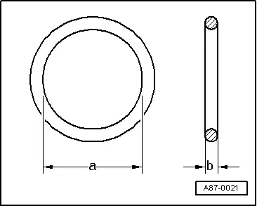
- Install only O-rings that are resistant to refrigerant R134a and corresponding refrigerant oil. The O-ring seals are color-coded to avoid mistakes (currently "red", "light purple" or "dark purple"). Refer to the Parts Catalog.
- The dimensions -a- and -b- are different depending on installation location of the O-ring seals. Refer to the Parts Catalog.
- In addition to the color-coded O-ring seals, use is also made at the factory of black O-ring seals for certain connections.
READ NEXT:
 Actuator Information
Actuator Information
Caution
A/C system (heater) malfunctions
A/C system malfunctions can occur if the actuator
and/or the corresponding connectors are switched.
A/C system (heater
Technical Data
Refrigerant R134a Capacities
Refrigerant R134a and refrigerant oil. Refer to
→ Refrigerant R134a Servicing; Rep. Gr.87; Refrigerant R134a
Capacities, Refrigerant Oil and Approved
Heating, Ventilation
Component Location Overview - Heating
Component Location Overview - Components Outside of Passenger
Compartment
Note
At the start of production, only one Air Conditioning (A/C)
systSEE MORE:
Overview - Front Three-Point Seat Belt
Overview - Front Three-Point Seat Belt, USA and Canada Market
1 - Belt End Fitting Cover
Removing and installing. Refer to
→ Chapter "Front Belt End Fitting, Removing and Installing, USA and
Canada Market-Specific".
2 - Bolt
45 Nm
If it was removed
Component Location Overview - Luggage Compartment Trim Panels
1 - Lock Carrier Trim
Overview. Refer to
→ Chapter "Overview - Lock Carrier Trim".
2 - Luggage Compartment Floor Covering
Overview. Refer to
→ Chapter "Overview - Luggage Compartment Floor".
3 - Luggage Compartment Side Trim Panel
O