Audi Q3: Battery Tray, Removing and Installing
Battery Tray, Removing and Installing, Version 1
Removing
- Remove the air filter housing. Refer to → Rep. Gr.23; Air Filter; Air Filter Housing, Removing and Installing or → Rep. Gr.24; Air Filter; Air Filter Housing, Removing and Installing.
- Remove the battery. Refer to → Chapter "Battery in Engine Compartment, Removing and Installing, Version 1".
- Free up the wire from the battery tray.
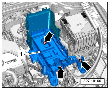
- Remove the bolts -arrows-.
- Remove the battery tray -1-.
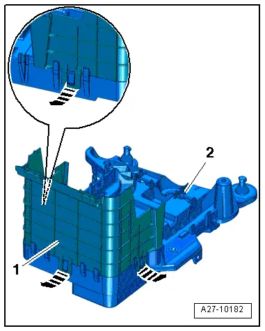
- Release the clips in direction of -arrows- and remove the rear battery jacket -1- on the battery tray -2-.
Installing
Install in reverse order of removal. Note the following:
- Install the battery. Refer to → Chapter "Battery in Engine Compartment, Removing and Installing, Version 1".
- Install the air filter housing. Refer to → Rep. Gr.23; Air Filter; Overview - Air Filter Housing or → Rep. Gr.24; Air Filter; Overview - Air Filter Housing.
Battery Tray, Removing and Installing, Version 2
Removing
- Remove the battery. Refer to → Chapter "Battery in Engine Compartment, Removing and Installing, Version 2".
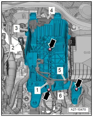
- Free up the grommets -1, 4 and 5- for the wire from the battery tray.
- Free up the wire from the battery tray.
- If equipped, free up the transmission ventilation -2- from the battery tray.
- Remove the bolts -arrows-.
- Remove the battery tray -3-.
Installing
Install in reverse order of removal. Note the following:
- Install the battery. Refer to → Chapter "Battery in Engine Compartment, Removing and Installing, Version 2".
READ NEXT:
 Battery, Charging
Preparing for Charging, Engine Compartment Battery
Procedure
WARNING
Risk of explosion on discharged battery with "Visual
indicator".
If the "Visual indicator" has no color or is light
Battery Jump Start Terminal
Overview - Battery Jump Start Terminal
1 - Bolt
6 Nm
2 - Battery Jump Start Terminal -U6-
With positive terminal grip
Removing and installing. Refer to
→ C
Start/Stop System
Component Location Overview - Start/Stop System
1 - Bracket
For the Voltage Stabilizer -J532-
2 - Connector
3 - Voltage Stabilizer -J532-
Removing and inst
SEE MORE:
Mobile Online Services
Overview - Mobile Online Services
The Internet Access Control Module -J666- (Audi music
interface online, UE2) expands the External Audio Source
Connection -R199- (AMI) using the following functions:
Register web radio stations and Podcasts using the WLAN-Home
Network and play them in the
Overview - Radiator Grille
Overview - Radiator Grille, Vehicles through MY 2014
1 - Audi Rings
Removing and installing. Refer to
→ Chapter "Front Emblem, Removing and Installing".
2 - Right Mount
For the parking aid sensor
Removing and installing. Refer to
→ Chapter "Front
