Audi Q3: Component Location Overview - Instrument Panel Controls
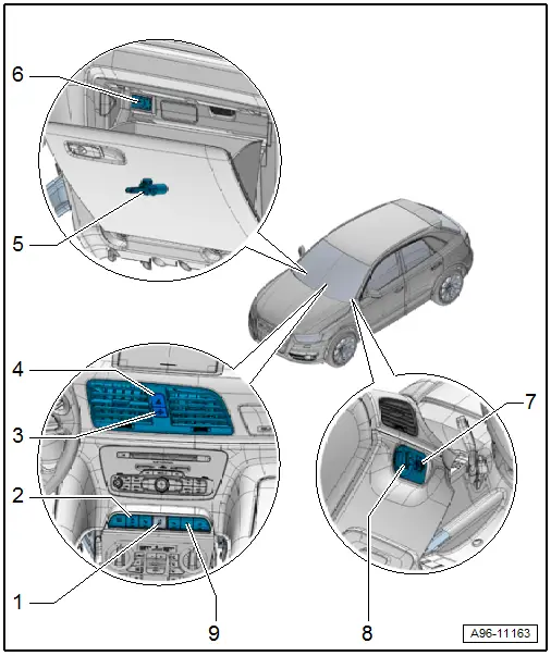
1 - ASR/ESP Button -E256-
- Removing and installing. Refer to → Chapter "ASR/ESP Button -E256-, Removing and Installing".
2 - Left Lower Button Unit
- Equipment level
- With Driving Profile Selection Switch Module -E592-, Start/Stop Mode Button -E693-, Parallel Parking Assistance Button -E581-
- Removing and installing. Refer to → Chapter "Lower Left Instrument Panel Button Unit, Removing and Installing".
3 - Front Passenger Airbag -Disabled- Indicator Lamp -K145-
- Equipment level
- Is in one housing with the Emergency Flasher Button -E229- and cannot be replaced separately if faulty.
- Removing and installing. Refer to → Chapter "Emergency Flasher Button -E229-, Removing and Installing".
4 - Emergency Flasher Button -E229-
- Removing and installing. Refer to → Chapter "Emergency Flasher Button -E229-, Removing and Installing".
5 - Glove Compartment Lamp Switch -E26-
- Removing and installing. Refer to → Chapter "Glove Compartment Lamp Switch -E26-, Removing and Installing".
6 - Front Passenger Airbag Deactivation Key Switch -E224-
- Removing and installing. Refer to → Body Interior; Rep. Gr.69; Passenger Airbag; Front Passenger Airbag Deactivation Key Switch Removing and Installing.
7 - Controls/Switch Unit
- With Instrument Panel and Switch Illumination Dimmer Switch -E20-, Headlamp Range Control Adjuster -E102-
- Removing and installing. Refer to → Chapter "Instrument Panel and Switch Illumination Dimmer Switch -E20-, Removing and Installing".
8 - Light Switch -E1-
- With Fog Lamp and Rear Fog Lamp Switch -E23-
- Removing and installing. Refer to → Chapter "Light Switch -E1-, Removing and Installing".
9 - Right Lower Button Unit
- Equipment level
- With Parking Aid Button -E266-, Hill Descent Control Button -E618-
- Removing and installing. Refer to → Chapter "Lower Right Instrument Panel Button Unit, Removing and Installing".
Component Location Overview - Front Door Controls
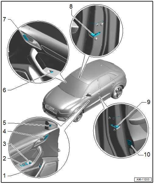
1 - Rear Lid Unlock Switch -E165-
- Removing and installing. Refer to → Chapter "Rear Lid Unlock Switch -E165-, Removing and Installing".
2 - Power Window Control Head In Driver Door -E512-
- with Left Front Window Regulator Switch -E40- and Driver Right Front Window Regulator Switch -E81-
- With Left Rear Window Regulator Switch in Driver Door -E53-, Right Rear Window Regulator Switch in Driver Door -E55- and Central Window Regulator Switch in Driver Door -E189-
- Window regulator switch, removing and installing. Refer to → Chapter "Power Window Control Head In Driver Door -E512-, Removing and Installing".
3 - Mirror Adjusting Switch
- Mirror Adjusting Switch -E43- or Folding Mirror Adjustment Switch -E168-
- Removing and installing. Refer to → Chapter "Mirror Adjusting Switch -E43-/Folding Mirror Adjustment Switch -E168-, Removing and Installing".
4 - Driver Interior Locking Button -E308-
- Removing and installing. Refer to → Chapter "Driver Interior Locking Button -E308-, Removing and Installing".
5 - Lane Change Assistance Button -E530-
- Overview. Refer to → Chapter "Overview - Lane Change Assistance".
6 - Front Passenger Door Window Regulator Switch -E107-
- Removing and installing. Refer to → Chapter "Front Passenger Door Window Regulator Switch -E107-, Removing and Installing".
7 - Front Passenger Interior Locking Button -E309-
- Removing and installing. Refer to → Chapter "Driver Interior Locking Button -E308-, Removing and Installing".
8 - Front Passenger Door Contact Switch -F3-
- Integrated in the door lock. Cannot be replaced separately if faulty.
- Door lock, removing and installing. Refer to → Body Exterior; Rep. Gr.57; Door Components: Door Lock, Removing and Installing.
9 - Driver Door Contact Switch -F2-
- Integrated in the door lock. Cannot be replaced separately if faulty.
- Door lock, removing and installing. Refer to → Body Exterior; Rep. Gr.57; Door Components: Door Lock, Removing and Installing.
10 - Interior Monitoring Switch -E183-
- Overview. Refer to → Chapter "Overview - Interior Monitoring".
Component Location Overview - Rear Door Controls
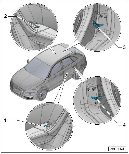
1 - Left Rear Power Window Switch in Left Rear Door -E52-
- Removing and installing. Refer to → Chapter "Left Rear Power Window Switch in Left Rear Door -E52-/ Right Rear Window Switch in Right Rear Door -E54-, Removing and Installing".
2 - Right Rear Window Switch in Right Rear Door -E54-
- Removing and installing. Refer to → Chapter "Left Rear Power Window Switch in Left Rear Door -E52-/ Right Rear Window Switch in Right Rear Door -E54-, Removing and Installing".
3 - Right Rear Door Contact Switch -F11-
- Integrated in the door lock. Cannot be replaced separately if faulty.
- Door lock, removing and installing. Refer to → Body Exterior; Rep. Gr.58; Door Components: Door Lock, Removing and Installing.
4 - Left Rear Door Contact Switch -F10-
- Integrated in the door lock. Cannot be replaced separately if faulty.
- Door lock, removing and installing. Refer to → Body Exterior; Rep. Gr.58; Door Components: Door Lock, Removing and Installing.
READ NEXT:
 Component Location Overview - Center Console Controls
1 - Access/Start Authorization Button -E408-
Removing and installing. Refer to
→ Chapter "Access/Start Authorization Button -E408-, Removing and
Installing".
2 -&nbs
Light Switch -E1-, Removing and Installing
Removing
- Turn the light switch to position "0".
- Push the light switch in direction of
-arrow A- and turn right at the same time in direction of
-arrow B-.
- Hold the switch in
Power Window Control Head In Driver Door -E512-, Removing and Installing
Removing
- Remove the pull handle with the switch mount. Refer to
→ Body Interior; Rep. Gr.70; Door Trim Panels; Front Pull
Handle, Removing and Installing.
- Carefully
SEE MORE:
Receiver/Dryer or Accumulator and Restrictor, Replacing after Cleaning
Refrigerant Circuit
Note
Cleaning the refrigerant circuit means flushing it with
refrigerant R134a. Refer to
→ Chapter "Refrigerant Circuit, Cleaning (Flushing), with
Refrigerant R134a" or blowing through with compressed
air and nitrogen. Refer to
→ Chapter "Refrigerant Circuit, Flushi
Front Backrest, Removing and Installing
Backrest Cover, Removing and Installing
Removing
WARNING
Danger of being injured by burrs on the backrest
cover.
Wear protective gloves.
- Reach behind the backrest cover -1-
and pull the cover off the backrest frame to the right as
illustrated.
Note
If this is d
