Audi Q3: Component Location Overview - Relay Carriers, Fuse Panels and E-Boxes
Overview - E-box, Wire Junction, Fuse Panel, Suppressor
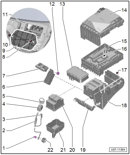
1 - Nut
- 9 Nm
2 - Wiring Harness
3 - Nut
- 4.5 Nm
4 - Suppressor -C24-
- Removing and installing. Refer to → Chapter "Suppressor -C24-, Removing and Installing".
5 - Bracket
- For the suppressor.
6 - Relay
- Equipment level
- Allocation. Refer to → Wiring diagrams, Troubleshooting & Component locations.
7 - Relay carrier under the E-box
- Equipment level
- Allocation. Refer to the Parts Catalog.
- Removing and installing. Refer to → Chapter "E-Box, Removing and Installing".
8 - Nut
- 3 Nm
9 - Cover
- For the plenum chamber connector station
- Removing and installing. Refer to → Chapter "Plenum Chamber Connector Station Cover, Removing and Installing".
10 - Nut
- 3 Nm
11 - Body
- To the vehicle interior
12 - Screw
- 2.4 Nm
13 - 40-Pin-Connector
- Removing and installing. Refer to → Chapter "E-Box, Removing and Installing".
14 - Cover
- for E-box
15 - Relay and Fuse Panel B -SB-
- with Fuse Panel A -SA-
- Removing and installing. Refer to → Chapter "Relay and Fuse Panel B -SB- in the E-Box, Removing and Installing".
16 - Bolt
- 9 Nm
- With permanent relay and Fuse Panel B -SB-
17 - Nut
- 6 Nm
18 - E-Box
- Removing and installing. Refer to → Chapter "E-Box, Removing and Installing".
19 - Cable Holder
20 - Mounting Box - Upper Section
- For the suppressor.
21 - Mounting Box - Lower Section
- For the suppressor.
22 - Anti-Twist Mechanism
- For the wire eye
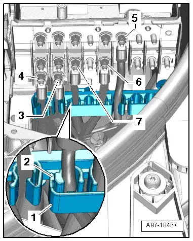
Tightening Specifications Fuse Panel A -SA- on the Left Engine Compartment E-box
- Tighten the nuts -6 and 7- to 4.5 Nm.
- Tighten the nuts -3, 4 and 5- to 6 Nm.
Overview - Instrument Panel Relay Carrier/Fuse Carrier and A-Pillar Relay Carrier/Fuse Carrier
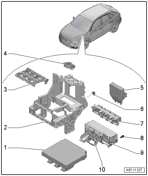
1 - Vehicle Electrical System Control Module -J519-
- Component location overview. Refer to → Chapter "Component Location Overview - Control Modules".
2 - Mount
- For the relay and fuse panel control module
- Removing and installing. Refer to → Chapter "Relay/Fuse Carrier Mount with Vehicle Electrical System Control Module -J519-, Removing and Installing".
3 - Relay Carrier Under Left Instrument Panel
- Removing and installing. Refer to → Chapter "Relay Carrier, Under Instrument Panel on Left Side, Removing and Installing".
4 - Front Parking Aid Warning Buzzer -H22-
- Overview. Refer to → Chapter "Overview - Parking Aid".
5 - Vehicle Positioning System Interface Control Module -J843-
- Removing and installing. Refer to → Body Exterior; Rep. Gr.57; Central Locking; Central Locking Component Location Overview.
6 - Nut
- 4.5 Nm
- Quantity: 2
7 - Vehicle Electrical System Control Module Relay Panel
- Removing and installing. Refer to → Chapter "Relay Carrier on Vehicle Electrical System Control Module, Removing and Installing".
8 - Screw
- 2.5 Nm
- Quantity: 2
9 - Fuse Panel C -SC-
- Removing and installing. Refer to → Chapter "Fuse Panel C -SC-, Removing and Installing".
10 - Mount
- For 16-Pin Connector -T16-
READ NEXT:
 E-Box, Removing and Installing
Removing
- Remove the relay and fuse panel and move them to the side
with the wires still connected. Refer to
→ Chapter "Relay and Fuse Panel B -SB- in the E-Box, Removing
and Insta
Relay and Fuse Carriers Behind Instrument Panel on Driver Side, Removing and
Installing
Relay Carrier on Vehicle Electrical System Control Module, Removing and
Installing
Removing
- Remove the driver side instrument panel cover. Refer to
→ Body Interior; Rep. Gr.68;
Control Modules
Component Location Overview - Control Modules
Component Location Overview - Control Modules
1 - Vehicle Electrical System Control Module -J519-
Removing and installing. Refer to
â†
SEE MORE:
Digital compass
Switching the compass on and off
Applies to: vehicles with digital compass
Fig. 48 Rearview mirror: digital compass is switched on
To turn the compass on or off, press the button
1 until the compass display in the mirror turns
on or off.
The digital compass only works when the ignition
is turn
Traffic incidents
Introduction
Applies to: vehicles with navigation system and online traffic
information
Fig. 135 Traffic information overview
Open traffic information
Requirement: the map must be displayed.
Press on the traffic jam symbol in the side
menu on the map fig. 131.
Display traffic report details
