Audi Q3: Relay and Fuse Carriers Behind Instrument Panel on Driver Side, Removing and Installing
Relay Carrier on Vehicle Electrical System Control Module, Removing and Installing
Removing
- Remove the driver side instrument panel cover. Refer to → Body Interior; Rep. Gr.68; Storage Compartments/Covers; Driver Side Instrument Panel Cover, Removing and Installing.
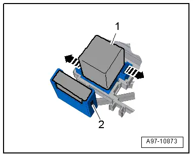
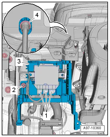
- Release the tab -3- with a screwdriver and remove the relay panel -2- from the vehicle electrical system control module -1-.
 Note
Note
Disregard -2-.

- Open the retainers in direction of -arrows- and remove the relay -1- and the control modules from the relay carriers.
 Note
Note
Check the exact assignment in the current wiring diagram. Refer to → Wiring diagrams, Troubleshooting & Component locations.
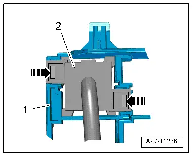
- Release the retainers -arrows- and remove the relay carrier -2- from the relay/fuse panel -1- to the rear.
Installing
Install in reverse order of removal. Note the following:
- Install the driver side instrument panel cover. Refer to → Body Interior; Rep. Gr.68; Storage Compartments/Covers; Driver Side Instrument Panel Cover, Removing and Installing.
Relay Carrier, Under Instrument Panel on Left Side, Removing and Installing
Removing
- Remove the vehicle electrical system control module. Refer to → Chapter "Vehicle Electrical System Control Module -J519-, Removing and Installing".
- Disengage the relay panel -2- from the mount -1- downward, to do this push the springs in the direction of -arrow-.
 Note
Note
Disregard -2-.
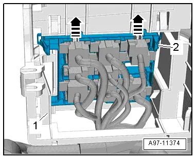
- Open the retainers -arrows- and remove the relay -1- and the control modules from the relay carriers.
 Note
Note
Check the exact assignment in the current wiring diagram. Refer to → Wiring diagrams, Troubleshooting & Component locations.

- Release the retainers -arrows- and remove the relay carrier -2- from the relay/fuse panel -1- to the rear.
Installing
Install in reverse order of removal. Note the following:
- Install the vehicle electrical system control module. Refer to → Chapter "Vehicle Electrical System Control Module -J519-, Removing and Installing".

Relay/Fuse Carrier Mount with Vehicle Electrical System Control Module -J519-, Removing and Installing
Removing
- Remove the fuse panel C and set aside with the wires still attached. Refer to → Chapter "Fuse Panel C -SC-, Removing and Installing".
- Remove the vehicle electrical system control module and set aside with the wires attached and if equipped with the relay carrier still attached. Refer to → Chapter "Vehicle Electrical System Control Module -J519-, Removing and Installing".
- Remove the relay carrier under left instrument panel. Refer to → Chapter "Relay Carrier, Under Instrument Panel on Left Side, Removing and Installing".
- Remove the instrument cluster. Refer to → Chapter "Instrument Cluster with Instrument Cluster Control Module -J285-, Removing and Installing".
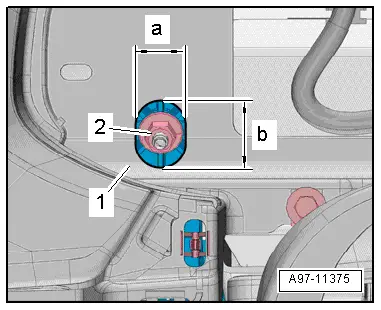
- To reach the upper nut -2- from the mount for the control modules, relay and fuse panel, drill an oblong hole into the instrument cluster mount -1- as shown.
- Dimension -a- = 22 mm.
- Dimension -b- = 23 mm.
- Remove the nuts -2 and 4-.
- If equipped disconnect the connector -1- on the vehicle positioning system interface control module.
- If equipped disconnect the connector on the buzzer.
- Disengage the mount -3- for the control module, relay and fuse panel from the instrument panel central tube and remove.
Installing
Install in reverse order of removal. Note the following:
- Install the relay carrier under left instrument panel. Refer to → Chapter "Relay Carrier, Under Instrument Panel on Left Side, Removing and Installing".
- Install the vehicle electrical system control module. Refer to → Chapter "Vehicle Electrical System Control Module -J519-, Removing and Installing".
- Install fuse panel C. Refer to → Chapter "Fuse Panel C -SC-, Removing and Installing".
READ NEXT:
 Control Modules
Component Location Overview - Control Modules
Component Location Overview - Control Modules
1 - Vehicle Electrical System Control Module -J519-
Removing and installing. Refer to
â†
Connectors
Connector Component Location Overview
1 - Right Front Door Cut-Off Connector
Disconnecting. Refer to
→ Chapter "Left Door Cut-Off Connector, Disconnecting".
2 -
SEE MORE:
A/C System Repair Information
Air conditioning systems designed for refrigerant R12 are
only to be filled with refrigerant R134a if certain requirements
are fulfilled. Refer to
→ Chapter "Refrigerant Circuit, Converting R12 to R134a and
Servicing" and Repair manual: Air Conditioner with
R12 Parts 2 and 3. Thi
High Pressure Sensor -G65-, Removing and Installing
Note
When the High Pressure Sensor -G65- is removed, the cooling
output cannot be checked. The Climatronic Control Module
-J255-/A/C Control Module -J301- control head does not switch on
the Air Conditioning (A/C) compressor. Refer to Vehicle
Diagnostic Tester in the "Guided Fau
