Audi Q3: Control Modules
Component Location Overview - Control Modules
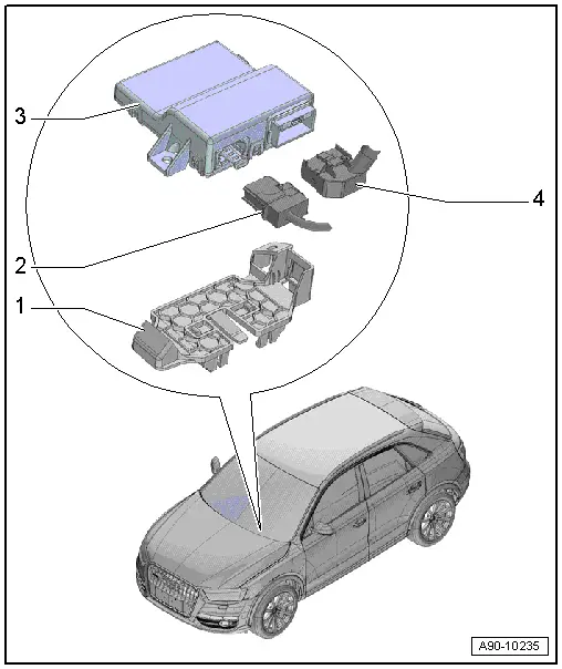
Component Location Overview - Control Modules

1 - Vehicle Electrical System Control Module -J519-
- Removing and installing. Refer to → Chapter "Vehicle Electrical System Control Module -J519-, Removing and Installing".
2 - Mount
- For the relay and fuse panel control module
3 - Relay Carrier under Left Instrument Panel
4 - Front Parking Aid Warning Buzzer -H22-
- Overview. Refer to → Chapter "Overview - Parking Aid".
5 - Vehicle Positioning System Interface Control Module -J843-
- Removing and installing. Refer to → Body Exterior; Rep. Gr.57; Central Locking; Central Locking Component Location Overview.
6 - Nut
- Tightening specification. Refer to → Chapter "Overview - Instrument Panel Relay Carrier/Fuse Carrier and A-Pillar Relay Carrier/Fuse Carrier".
- Quantity: 2
7 - Vehicle Electrical System Control Module Relay Panel
- Removing and installing. Refer to → Chapter "Relay Carrier on Vehicle Electrical System Control Module, Removing and Installing".
8 - Bolt
- Tightening specification. Refer to → Chapter "Overview - Instrument Panel Relay Carrier/Fuse Carrier and A-Pillar Relay Carrier/Fuse Carrier".
- Quantity: 2
9 - Fuse Panel C -SC-
- Overview. Refer to → Chapter "Overview - Instrument Panel Relay Carrier/Fuse Carrier and A-Pillar Relay Carrier/Fuse Carrier".
10 - Mount
- For 16-Pin Connector -T16-
Component Location Overview - Data Bus on Board Diagnostic Interface
1 - Mount
- For Data Bus On Board Diagnostic Interface -J533-
- Removing and installing. Refer to → Chapter "Data Bus On Board Diagnostic Interface -J533-, Removing and Installing".
2 - Fiber Optic Cable Connector
- Seal with Fiber-Optic Repair Set - Connector Protective Caps -VAS6223/9-
3 - Data Bus On Board Diagnostic Interface -J533-
- There are different versions. Refer to the Parts Catalog.
- Removing and installing. Refer to → Chapter "Data Bus On Board Diagnostic Interface -J533-, Removing and Installing".
4 - Connector
- For Data Bus On Board Diagnostic Interface -J533-
Vehicle Electrical System Control Module -J519-, Removing and Installing
- If replacing the control module, select the "Replace Control Module" function see Vehicle Diagnostic Tester.
Removing
- Remove the fuse panel C and set aside with the wires still attached. Refer to → Chapter "Fuse Panel C -SC-, Removing and Installing".
- If equipped, remove the relay carrier from the vehicle electrical system control module and with the lines still connected and move it to the side. Refer to → Chapter "Relay Carrier on Vehicle Electrical System Control Module, Removing and Installing".
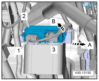
- Disconnect the connectors -2 through 4-.
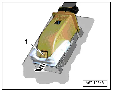
- To disconnect the connector, press the tab -1-, turn the retaining bracket in direction of -arrow- and remove the connector.
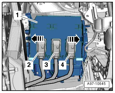
- Release the springs in direction of -arrows- and remove the vehicle electrical system control module -1- from the base mount downward.
Installing
Install in reverse order of removal. Note the following:
- Install the relay carrier on the vehicle electrical system control module. Refer to → Chapter "Relay Carrier on Vehicle Electrical System Control Module, Removing and Installing".
- Install fuse panel C. Refer to → Chapter "Fuse Panel C -SC-, Removing and Installing".

Data Bus On Board Diagnostic Interface -J533-, Removing and Installing
Special tools and workshop equipment required
- Fiber-Optic Repair Set - Connector Protective Caps -VAS6223/9- from Fiber-Optic Repair Set -VAS6223B-
- If replacing the control module, select the "Replace Control Module" function see Vehicle Diagnostic Tester.
Removing
- Remove the driver side instrument panel cover. Refer to → Body Interior; Rep. Gr.68; Storage Compartments/Covers; Driver Side Instrument Panel Cover, Removing and Installing.
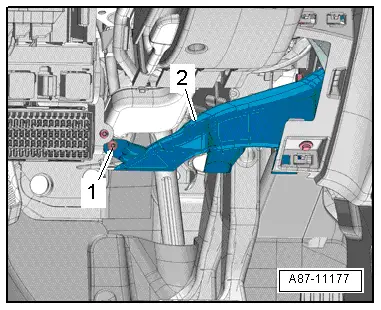
- Remove the bolt -1-.
- Remove the footwell vent -2-.
- Open the tab in direction of -arrow A- and pivot the Data Bus On Board Diagnostic Interface -J533--2- from the mount and remove in direction of -arrow B-.
- Disconnect the connector -3-.
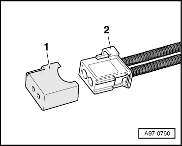
- If equipped, disconnect the connector -1- for the fiber-optic cable.
- Seal open wiring harness connector -2- with Fiber-Optic Repair Set - Connector Protective Caps -VAS6223/9--1-.
 Note
Note
The protective cap prevents contamination of or mechanical damage to end face of fiber optic cable which would impair signal transmission.
Remove the Data Bus On Board Diagnostic Interface -J533- Mount:
- Remove the data bus on board diagnostic interface. Refer to → Chapter "Data Bus On Board Diagnostic Interface -J533-, Removing and Installing".
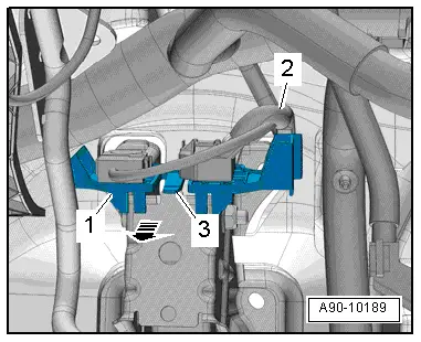
- Free up the wiring harness -2-.
- Open the tab -3- and remove the mount -1- from the pedal assembly in direction of -arrow-.
Installing
Install in reverse order of removal. Note the following:
- Install the driver side footwell vent. Refer to → Heating, Ventilation and Air Conditioning; Rep. Gr.87; Air Duct; Overview - Air Ducts and Air Distribution in Passenger Compartment.
- Install the driver side instrument panel cover. Refer to → Body Interior; Rep. Gr.68; Storage Compartments/Covers; Driver Side Instrument Panel Cover, Removing and Installing.
READ NEXT:
 Connectors
Connector Component Location Overview
1 - Right Front Door Cut-Off Connector
Disconnecting. Refer to
→ Chapter "Left Door Cut-Off Connector, Disconnecting".
2 -
General, Technical data
Safety Precautions
Safety Precautions when Working on Start/Stop System
Pay Attention to the Following when Working On Vehicles with
a Start/Stop System:
WARNING
Danger of personal inj
SEE MORE:
Special Tools
Special tools and workshop equipment
required
Shock Absorber Set -T10001-
Tensioning Strap -T10038-
Tripod Joint Tool -T10065-
Locating Pins -T10096-
Engine/Gearbox Jack Adapter - Wheel Hub Support -T10149-
Socket - Xzn 18 -T10162-
Bearing Installer -
Trailing Arm, Servicing
Trailing Arm, Servicing, FWD Vehicles
Special tools and workshop equipment
required
Press Plate -VW401-
Press Plate -VW402-
Front Subframe Mount Kit -3372-
Hydraulic Press - Bushing Assembly Tool Kit -T10230-
Pressing out the bonded rubber bushing
- Remove trailing arm with mou
