Audi Q3: Front Exterior Door Handle Switch, Removing and Installing
Removing
- Remove the exterior door handle. Refer to → Body Exterior; Rep. Gr.57; Door Components; Door Handle, Removing and Installing.
 Note
Note
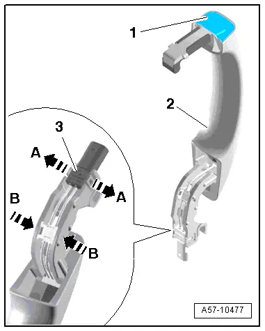
Ignore -1 and 2-.
- Release the retaining tabs in direction of -A arrows- and remove the connector -3-.
- Carefully release the retaining hooks in direction of -B arrows- using a small screwdriver and remove the wiring guide.
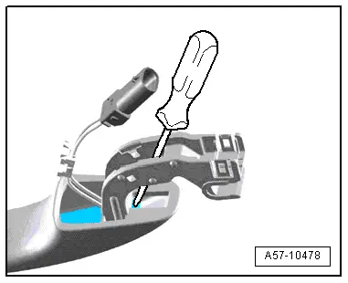
- Position a large stabile screwdriver on the outside door handle as illustrated.
- Remove the exterior door handle touch sensor forward out of the retainer on the exterior door handle using force.
- Remove the outside door handle touch sensor from the handle.
Installing
Install in reverse order of removal. Note the following:
- Slide the outside door handle touch sensor in until it engages audibly.
- Install the exterior door handle. Refer to → Body Exterior; Rep. Gr.57; Door Components; Door Handle, Removing and Installing.
Access/Start Authorization Control Module -J518-, Removing and Installing
- If replacing the control module, select the "Replace Control Module" function Vehicle Diagnostic Tester.
Removing
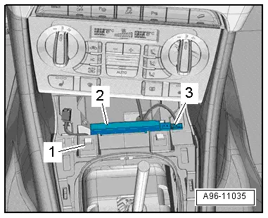
- Remove the glove compartment. Refer to → Body Interior; Rep. Gr.68; Storage Compartment/Covers; Glove Compartment, Removing and Installing.
- Open the tab -3- and remove the control module -2- from the bracket -4--arrow-.
- Disconnect the connector -1-.
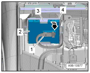
- To disconnect the connector, press the tab -1-, turn the retaining bracket in direction of -arrow- and remove the connector.
Installing
Install in reverse order of removal. Note the following:
- Install the glove compartment. Refer to → Body Interior; Rep. Gr.68; Storage Compartment/Covers; Glove Compartment, Removing and Installing.
Access/Start System Antenna 1 in Vehicle Interior -R138-, Removing and Installing
Removing
- Remove the front storage compartment. Refer to → Body Interior; Rep. Gr.68; Center Console; Front Center Console Storage Compartment, Removing and Installing.
 Note
Note
- Depending on the version, the Access/Start System Antenna 1 in Vehicle Interior -R138- can be located under or behind the A/C display control head, Climatronic Control Module -J255-
- Remove the A/C display control head, Climatronic Control Module -J255-. Refer to → Heating, Ventilation and Air Conditioning; Rep. Gr.87; Display and Control Head; Display and Control Head, Removing and Installing.
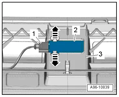
- Disconnect the connector -3-.
- Remove the antenna -2- upward from the mount.
Installing
Install in reverse order of removal, while paying attention to the following:
- Remove the front storage compartment. Refer to → Body Interior; Rep. Gr.68; Center Console; Front Center Console Storage Compartment, Removing and Installing.
- Depending on the version, install the A/C display control head, Climatronic Control Module -J255-. Refer to → Heating, Ventilation and Air Conditioning; Rep. Gr.87; Display and Control Head; Display and Control Head, Removing and Installing.
Driver Access/Start System Antenna -R134-, Removing and Installing
Removing
- Remove the underbody cover. Refer to → Body Exterior; Rep. Gr.66; Overview - Underbody Panel.
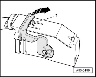
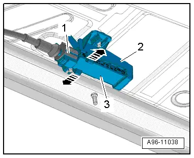
- Disconnect the connector -1-.
- open the clips in direction of -arrows- and remove the antenna -3- from the mount -2-.
Installing
Install in reverse order of removal. Note the following:
- Install the underbody cover. Refer to → Body Exterior; Rep. Gr.66; Overview - Underbody Panel.

Front Passenger Access/Start System Antenna -R135-, Removing and Installing
Removing
- Remove the underbody cover. Refer to → Body Exterior; Rep. Gr.66; Overview - Underbody Panel.
- Disconnect the connector -1-.
- open the clips in direction of -arrows- and remove the antenna -3- from the mount -2-.
Installing
Install in reverse order of removal. Note the following:
- Install the underbody cover. Refer to → Body Exterior; Rep. Gr.66; Overview - Underbody Panel.
Access/Start System Antenna in Luggage Compartment -R137-, Removing and Installing
Special tools and workshop equipment required
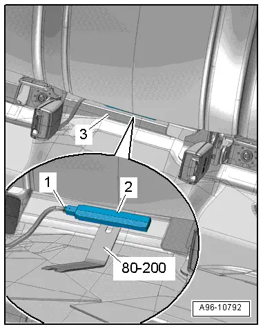
- Pry Lever -80-200-
Removing
- Remove the luggage compartment liner -3- or front luggage compartment floor. Refer to → Body Interior; Rep. Gr.70; Luggage Compartment Trim; Luggage Compartment Floor, Removing and Installing.
- Disconnect the connector -1-.
- Pry out the antenna -2- from the body using the Pry Lever -80-200-.
Installing
Install in reverse order of removal. Note the following:
- Install the luggage compartment liner or front luggage compartment floor. Refer to → Body Interior; Rep. Gr.70; Luggage Compartment Trim; Luggage Compartment Floor, Removing and Installing.
Access/Start System Antenna in Rear Bumper -R136-, Removing and Installing
Removing
- Remove the rear bumper cover. Refer to → Body Exterior; Rep. Gr.63; Rear Bumper; Bumper Cover, Removing and Installing.
- Disconnect the connector -1-.
- open the clips in direction of -arrows- and remove the antenna -2- from the mount -3-.
Installing
Install in reverse order of removal. Note the following:
- Install the rear bumper cover. Refer to → Body Exterior; Rep. Gr.63; Rear Bumper; Bumper Cover, Removing and Installing.
If the bumper cover was removed, the Lane Change Assistance Control Module -J769-/Lane Change Assistance Control Module 2 -J770- must be calibrated again. Refer to → Chapter "Lane Change Assistance, Calibrating".
READ NEXT:
 Overview - Steering Column Switch Module
Steering Column Switch Module Assembly Overview, with Mechanical Ignition
Switch
1 - Steering Column
2 - Bolt
Quantity: 2
For steering lock housing (shear bolt)
3&nb
Lock Cylinder, Removing and Installing
Create an assisting tool from a wire hook as follows:
- Take a 1.5 mm diameter welding wire and bend the end to form
an eye.
- Then cut the welding wire.
Dimension -a- = approximatel
Steering Column Switch Module, Removing and Installing
Steering Column Switch Module, Removing and Installing, with Mechanical
Ignition Lock
Removing
- Adjust steering wheel downward and to rear as far as
possible, use entire adjustment range o
SEE MORE:
Center Console, Removing and Installing
Center Console, Removing and Installing
Removing
- Remove the center console insert. Refer to
→ Chapter "Center Console Insert, Removing and Installing".
- Versions with Access/Start Authorization Button -E408-:
Remove the front storage compartment. Refer to
→ Chapter
Tachometer
The tachometer 2 displays the engine
speed in revolutions per minute (RPM). The beginning
of the red zone in the tachometer indicates
the maximum permissible engine speed for
all gears once the engine has been broken in. Before
reaching the red zone, you should shift into
the next higher gear, selec
