Audi Q3: Lock Cylinder, Removing and Installing
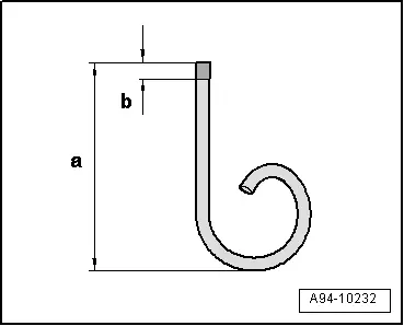
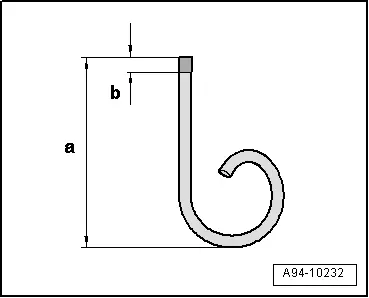
Create an assisting tool from a wire hook as follows:
- Take a 1.5 mm diameter welding wire and bend the end to form an eye.
- Then cut the welding wire.
- Dimension -a- = approximately 50 mm.
- File the end of the wire hook into a point.
- Dimension -b- = 3 mm
Removing
- Remove the steering column switch module trim panel. Refer to → Body Interior; Rep. Gr.68; Storage Compartments/Covers; Lower Steering Column Trim, Removing and Installing.
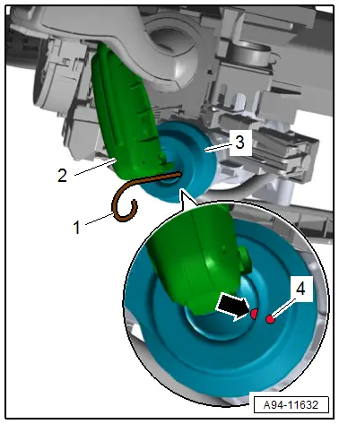
- Insert the ignition key into the lock cylinder and turn it to the ignition "on" position while doing this the hole -arrow- mark -4- must align with the ignition lock.
- Fold the ignition key -2- and hold it in this position as shown in the illustration.
- Insert the welding wire -1- all the way into the hole while pulling the lock cylinder -3- with the reader coil out of the steering lock housing.
- Disconnect the connector from the reader coil.
 WARNING
Risk of steering lock seizing.
Steering lock must not be operated without lock cylinder.
 Note
Note
- A seized steering lock must be replaced.
- When replacing the lock cylinder, follow the instructions regarding the immobilizer reader coil. Refer to → Electrical Equipment General Information; Rep. Gr.96; Immobilizer.
Installing
Install in the reverse order of removal. Note the following:
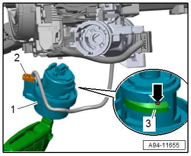
- Insert the ignition key into the lock cylinder -1- and turn it to the ignition "on" position.
- Push in the welding wire further in the front side opening until it stops, while doing so push the safety lever -3- until stop to the lock cylinder.
- The welding wire must poke out of the opening -arrow- in the safety lever.
- Connect the connector -2- to the anti-theft immobilizer reader coil.
- Insert the lock cylinder -1- with the reader coil into the steering lock housing.
- Remove the welding wire and push the lock cylinder in securely, until the safety lever engages audibly.
Ignition Switch Key Lock Solenoid -N376-, Removing and Installing
Removing
- Remove the trim for the steering column switch module. Refer to → Body Interior; Rep. Gr.68; Storage Compartments/Covers; Overview - Steering Column Trim Panel.
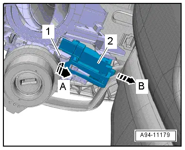
- Release the retainer in direction of -arrow A- and remove the Ignition Switch Key Lock Solenoid -N376--2- from the steering lock housing -1- in direction of -arrow B-.
Installing
Install in reverse order of removal. Note the following:
- Install the trim for the steering column switch module. Refer to → Body Interior; Rep. Gr.68; Storage Compartments/Covers; Overview - Steering Column Trim Panel.
Ignition/Starter Switch, Removing and Installing
Removing
- Remove the trim for the steering column switch module. Refer to → Body Interior; Rep. Gr.68; Storage Compartments/Covers; Overview - Steering Column Trim Panel.
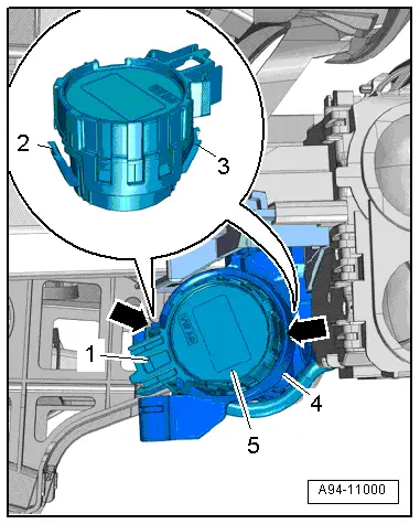
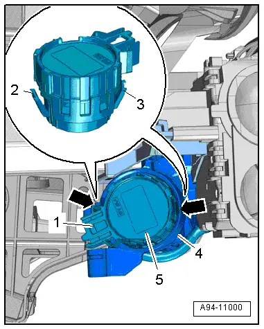
- Disconnect the connector -1-.
- Release the retainers -2 and 3- at the openings -arrows- in the steering lock housing -4- by inserting jeweler's screwdrivers.
If the procedure is not possible because there is not enough space, create an assisting tool from two wire hooks as follows.
- Bend the one end of a welding wire to form a 1 mm eye and cut down to the length -a-.
- Dimension -a- = approximately 50 mm.
- File the end of the wire hook into a point.
- Dimension -b- = 5 mm.
- Remove the Ignition/Starter Switch -D--Pos. 5- from the steering lock housing. The jeweler's screwdriver or wire hooks must remain inserted.
Installing
Install in reverse order of removal. Note the following:
- Push the Ignition/Starter Switch -D- into the steering lock housing until it engages audibly.
- Install the trim for the steering column switch module. Refer to → Body Interior; Rep. Gr.68; Storage Compartments/Covers; Overview - Steering Column Trim Panel.
