Audi Q3: Heater Core, Removing and Installing
Special tools and workshop equipment required
- Hose Clamps - Up To 25mm -3094-
- Engine Bung Set -VAS6122-
- Compressed air gun, commercially available
 Note
Note
Depending on the engine version to support the engine coolant pump an After-Run Coolant Pump -V51-/Heater Support Pump -V488- may be installed (different designations depending on the engine). Refer to → Engine Mechanical; Rep. Gr.19; Coolant System/Coolant (Connection Diagram for Coolant Hoses) and → Wiring diagrams, Troubleshooting & Component locations. The After-Run Coolant Pump -V51-/Heater Support Pump -V488- can be actuated in "stop mode" (engine stopped) to maintain the coolant flow rate through the heater core for the heater on with a cold engine or on vehicles with a Start/Stop System.
Removing
- For vehicles with a manual climate control system (heater without A/C system), adjust the temperature setting to "warm" via the knob -1- on the A/C Control Module -J301- (the Heater Control Module -J65-) control head.
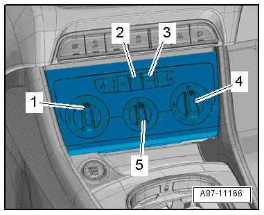
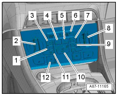
- For vehicles with an automatic climate control system, adjust the temperature setting for the driver- and front passenger side to "warm" via the knobs -2 and 8- on the Climatronic Control Module -J255- control head.
- "HI" in the display -6- on the Climatronic Control Module -J255-.
- Turn off the ignition.
 WARNING
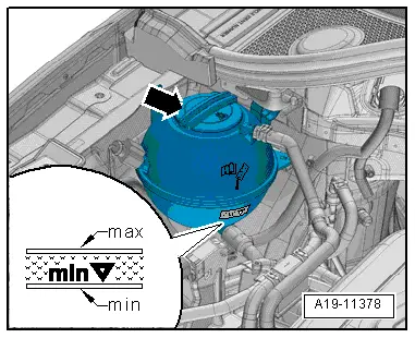
There is a risk of scalding from hot steam and coolant.
- The coolant system is under pressure when the engine is warm.
- To reduce the pressure, cover the coolant reservoir cap with several cloths and then open it carefully.
- Open the coolant reservoir cap -arrow-.
 Note
Note
Depending on engine and vehicle version, it may be necessary to loosen or to remove the following components: upper engine cover, compressed air pipe to throttle valve part and, depending on engine, the intake manifold, etc. Refer to → Engine Mechanical; Rep. Gr.21; Charge Air System; Overview - Charge Air System.
- For vehicles with a 5-cylinder engine (Audi RS Q3), remove the air guide pipe (from the air filter to the turbocharger). Refer to → Engine Mechanical; Rep. Gr.21; Overview - Charge Air System.
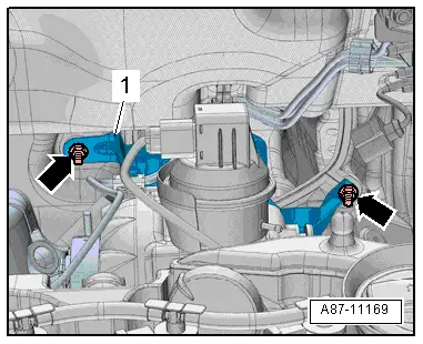
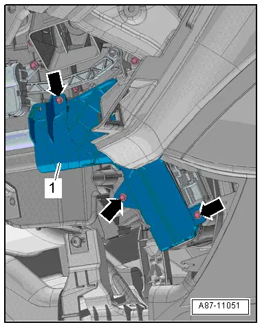
- If equipped, remove the nuts -arrows- and remove the heat shield -1-.
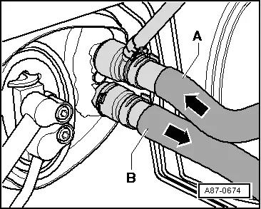
- Mark the layout of the coolant hoses -A and B-.
 Note
Note
The heater core is designed for a specific coolant flow direction -arrows-. Therefore, coolant hoses must be connected on the correct sides.
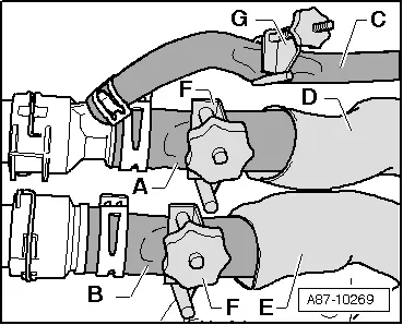
- Vehicles with gasoline engine: Slide the heat insulation -D and E- slightly back and clamp off the coolant hose -C- with Hose Clamps - Up To 25mm -3094--G-.
- Clamp off the coolant hoses -A and B- with Hose Clamps - Up To 25mm -3094--F- and remove them from the heater core by lifting the clips.
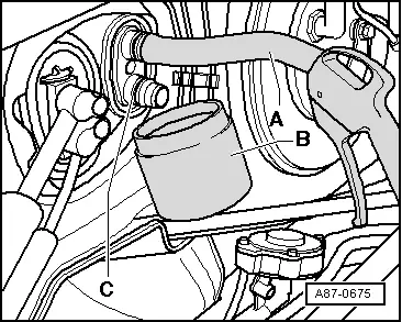
- Slide a short hose -A- onto the upper connection.
- Insert the compressed air gun into the end of the hose.
- Hold a container -B- under the lower connection -C- and carefully blow the coolant out of the heater core using the compressed-air gun.
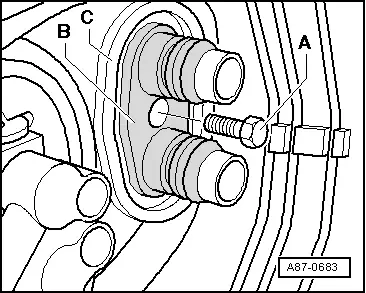
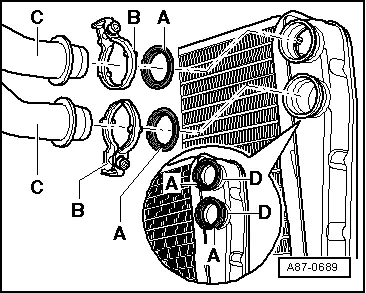
- Remove the bolt -A-.
- Remove the adapter -B- from the heater core connections.
- Seal the open lines and connections with clean plugs from the Engine Bung Set -VAS6122-.
 Note
Note
For RHD vehicles, the central tube must be removed instead of the driver side storage compartment. Refer to → Body Interior; Rep. Gr.70; Instrument Panel Central Tube; Instrument Panel Central Tube, Removing and Installing.
- Remove the driver side instrument panel cover. Refer to → Body Interior; Rep. Gr.68; Storage Compartments and Covers; Driver Side Instrument Panel Cover, Removing and Installing.
- Remove the left front footwell center console trim panel. Refer to → Body Interior; Rep. Gr.68; Center Console; Front Footwell Center Console Trim Panel, Removing and Installing.
- Remove the driver footwell vent. Refer to → Chapter "Driver Side Footwell Vent, Removing and Installing".
- Remove the bolts -arrows-.
- Remove the heater core cover -1-.
- Cover the carpet the in area under heat exchanger with waterproof foil and water absorbing paper.
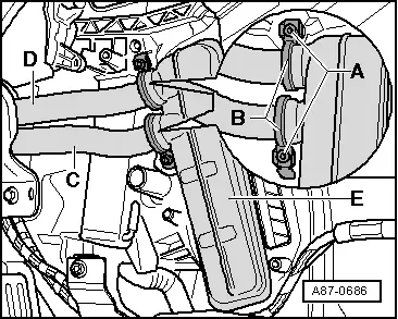
- Remove the bolts -A-.
- Remove the clamps -B-.
- Hold the container under the coolant pipes -C and D-.
- Remove the coolant pipes from the heater core -E- and carefully move to the side.
- Seal the open lines and connections with clean plugs from the Engine Bung Set -VAS6122-.

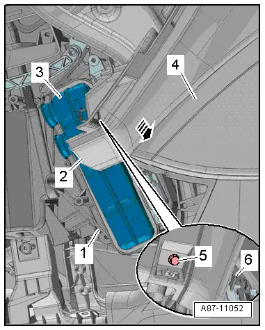
- Remove the bolt -5-.
 Caution
Risk of damaging the instrument panel.
- Only carefully remove the instrument panel from the central tube mount.
- A damaged instrument panel must be replaced. Instrument panel, replacing. Refer to → Body Interior; Rep. Gr.70; Instrument Panel; Instrument Panel, Removing and Installing.
- Disengage the instrument panel -2- at the center console -4- by lifting the instrument panel far enough until the mounts -6- free up.
- Pull the instrument panel approximately 30 mm in direction of -arrow- as shown and at the same time, pull the heater core -3- out of the air distribution housing.
Installing
Install in reverse order of removal. Note the following:
 Note
Note
Replace the O-ring.
- Make sure the grommet -C- is seated properly in the bulkhead partition.
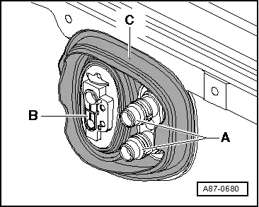
- With the heater core removed, check the heater shaft -A- for debris.
- If necessary, remove any dirt or coolant residue.
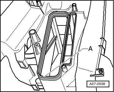
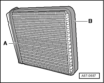
- Check the foam seals -A and B- attached to the heater core for damage; replacing if necessary.
 Note
Note
- Seal may curl up on insertion if not correctly bonded on.
- Cold air may flow past heater core if the foam seal is damaged or not properly fitted.
- Additional foam strips -A- are attached to the corners of the heater core -B-. These foam strips -A- are supposed to prevent any rattling noises, which are common on vehicles with a TDI engine.
- Attach the Foam Strips -191 819 069- on the heater cores.
- Remove any dirt or remaining coolant from the Air Conditioning (A/C) unit (heater), for example after removing a leaking heater core.
- Carefully slide the heater core all the way into the A/C unit (heater) until stop.
 Note
Note
When inserting the heater core, make sure that the connections and the coolant pipes are not damaged.

- Check the heater core connections and the coolant pipes for damage or debris.
- Clean the sealing surface for the O-ring and glaze it.
- Lightly moisten the new O-ring seals -A- with coolant (or lightly grease with silicone grease) and insert them into the heater core connections -D-.
- Slide the coolant pipes -C- into the heater core until stop.
 Caution
Risk of leaks at the heater core.
Crushed O-ring seals, sharp-edged or coolant pipes that have not been inserted completely may lead to leaks.
- Attach the new screw-type clamps -B- to the coolant pipe/heater core connection.
- Tighten the bolts -A-.
- Make sure that the grommet -C- sits in the groove on the adapter -B-.
- Slide the grommet onto the coolant pipes without tension.
- Tighten the bolt -A-.

 Note
Note
- Check the grommet and coolant pipes -A- on the bulkhead partition pass-through for proper seating.
- Damaged or incorrectly installed grommets will allow water to enter into the passenger compartment.
- For RHD vehicles, install the central tube and instrument panel. Refer to → Body Interior; Rep. Gr.70; Instrument Panel Central Tube; Instrument Panel Central Tube, Removing and Installing.
- Add coolant and bleed according to specification. Refer to → Engine Mechanical, Fuel Injection and Ignition; Rep. Gr.19; Cooling System/Coolant; Coolant, Draining and Filling.

Check the Connections at the Heater Core for Leaks:
- Carefully increase the pressure in the coolant circuit by using, for example, the hand pump of the Cooling System Tester -VAG1274B-.
- Check the coolant circuit for leaks, paying special attention to the connection between the coolant pipes -C and D- and the heater core -E-. Refer to → Engine Mechanical, Fuel Injection and Ignition; Rep. Gr.19; Cooling System/Coolant; Cooling System, Checking for Leaks.
 Note
Note
- When bleeding the coolant circuit, take special care to ensure complete bleeding of the heater core. If there are still air bubbles in the heater core, it may cause the customer to complain of insufficient heating output in winter or different air temperature from vents at same setting in regulated mode. Check the heating output: for manual climate control system (heater without A/C system, refer to → Chapter "Heating Output, Checking, Manual Climate Control System"; for automatic climate control system, refer to → Chapter "Heating Output, Checking, Automatic Climate Control System".
- Depending on vehicle equipment and on engine, heat insulation has been applied to coolant hoses, these must not be damaged and must be re-applied after installing.
- Install footwell vent on the driver side. Refer to → Chapter "Driver Side Footwell Vent, Removing and Installing".
- Install the left front footwell center console trim panel. Refer to → Body Interior; Rep. Gr.68; Center Console; Front Footwell Center Console Trim Panel, Removing and Installing.
- Install the driver side instrument panel cover. Refer to → Body Interior; Rep. Gr.68; Storage Compartments and Covers; Driver Side Instrument Panel Cover, Removing and Installing.
After completing the repair work, perform the following operations on the control head using the Vehicle Diagnostic Tester in the "Guided Fault Finding" function:
- Check the DTC memory and delete any currently displayed entries.
- Perform the basic setting.
- Perform output diagnostic test mode (DTM).
- Using the various settings on the Climatronic Control Module -J255-/A/C Control Module -J301- (the Heater Control Module -J65-) control head, adjust the airflow direction to various vents and check if the amount of air coming out of the vents actually changes according to the setting.

READ NEXT:
 Condensation Water Drain, Checking
Procedure
- Remove the glove compartment. Refer to
→ Body Interior; Rep. Gr.68; Storage Compartments and Covers;
Glove Compartment, Removing and Installing.
- Remove t
Overview - Air Routing and Air Distribution in Passenger Compartment
Overview - Air Routing and Air Distribution in Passenger Compartment,
Front Air Guides
1 - Screw
1.5 Nm
2 - Left Footwell Vent Air Guide - Driver Side
Removing
SEE MORE:
Overview - Radiator Grille
Overview - Radiator Grille, Vehicles through MY 2014
1 - Audi Rings
Removing and installing. Refer to
→ Chapter "Front Emblem, Removing and Installing".
2 - Right Mount
For the parking aid sensor
Removing and installing. Refer to
→ Chapter "Front
Battery Charger -VAS5903- Support Mode
General Information
The support mode provides the vehicle electrical system with
voltage when the Battery -A- is removed or disconnected.
For more information. Refer to the Battery Charger -VAS5903-
Operating Instructions.
The support mode is used for the following situations:
Vehicle ele
