Audi Q3: Humidity Sensor -G355-, Removing and Installing
Humidity Sensor -G355-, Removing and Installing, Vehicles without Driver Assistance Systems Front Camera
 Note
Note
- Only on vehicles with an automatic climate control system
- There are different versions. Refer to the Parts Catalog.
Removing
- Remove the interior rearview mirror. Refer to → Body Interior; Rep. Gr.68; Interior Rearview Mirror; Interior Rearview Mirror, Removing and Installing.
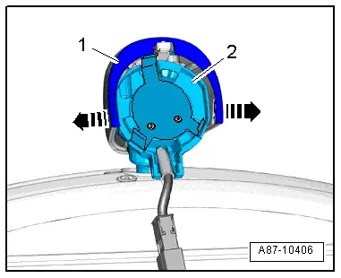
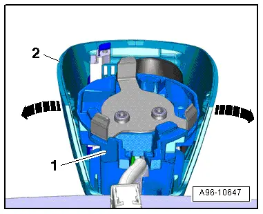
- Spread the cover -1- on both sides slightly -arrows- and remove it from the interior rearview mirror base -2-.
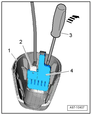
- Disconnect the connector -2-.
- Using a small screwdriver -3-, carefully press the Humidity Sensor -G355--item 4- off of the cover -1--arrow- and at the same time remove it upward.
Installing
Installation is done is reverse order, observe the following:
- Carefully insert the humidity sensor into the side guides.
 Note
Note
If the Humidity Sensor -G355- is not inserted correctly, the cover cannot be installed.
- Install the interior rearview mirror. Refer to → Body Interior; Rep. Gr.68; Interior Rearview Mirror; Interior Rearview Mirror, Removing and Installing.
Humidity Sensor -G355-, Removing and Installing, Vehicles with Driver Assistance Systems Front Camera
 Note
Note
- Only on vehicles with an automatic climate control system
- There are different versions. Refer to the Parts Catalog.
Removing
- Remove the interior rearview mirror. Refer to → Body Interior; Rep. Gr.68; Interior Rearview Mirror; Interior Rearview Mirror, Removing and Installing.
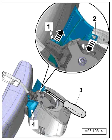
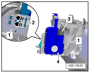
- Release the mounting tabs -1- and -2- using a screwdriver -3-.
- Disengage the rear cover -4-.
- Release the mounting tabs -arrows- and carefully fold the upper cover -2- slightly upward.
- Disengage the mounting tab -1- on the front cover -3-.
- Remove the upper cover.
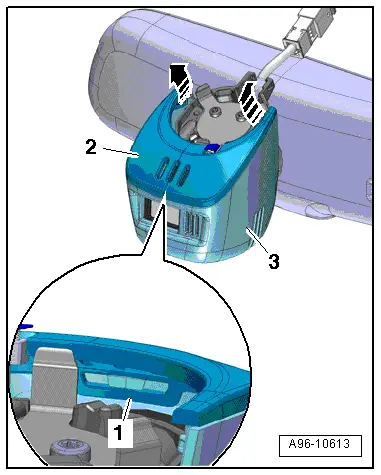
- Disengage the hooks in the direction of -arrow- and remove the front cover -2- downward from the guide braces on the rearview mirror base -1-.
- Release the clips -2--arrows- and remove the Humidity Sensor -G355--item 4- from the rearview mirror base -1-.
- Disconnect the connector -3-.
Installing
Installation is done is reverse order, observe the following:
- Install the interior rearview mirror. Refer to → Body Interior; Rep. Gr.68; Interior Rearview Mirror; Interior Rearview Mirror, Removing and Installing.
After-Run Coolant Pump -V51- / Heater Support Pump -V488-, Removing and Installing
 Note
Note
- Depending on the engine version to support the engine coolant pump an After-Run Coolant Pump -V51-/Heater Support Pump -V488- may be installed (different designations depending on the engine). Refer to → Engine Mechanical; Rep. Gr.19; Coolant System/Coolant (Connection Diagram for Coolant Hoses) and → Wiring diagrams, Troubleshooting & Component locations. The After-Run Coolant Pump -V51-/Heater Support Pump -V488- can be actuated in "stop mode" (engine stopped) to maintain the coolant flow rate through the heater core for the heater on with a cold engine or on vehicles with a Start/Stop System.
- Different versions depending on the engine After-Run Coolant Pump -V51-/Heater Support Pump -V488-.
- The After-Run Coolant Pump -V51-/Heater Support Pump -V488- is installed in the coolant circuit depending on the engine version. Refer to → Engine Mechanical; Rep. Gr.19; Coolant System/Coolant (Connection Diagram for Coolant Hoses) and → Wiring diagrams, Troubleshooting & Component locations.
To remove and install, refer to → Engine Mechanical; Rep. Gr.19; Coolant Pump/Thermostat (Overview - Electrical Coolant Pump).
Special Tools
Special tools and workshop equipment required
- Vehicle Diagnostic Tester
- Wrench - Door Adjusting - Joint -3320/1-
- Engine Bung Set -VAS6122-
- Ultrasound A/C Cleaner -VAS6189B-
- Ultrasound A/C Cleaner - Airco-Clean Fluid -VAS6189/1-
- Suction Nozzle With Brush -VAS6288-
- Dryer Element Plug Socket -T10128- for version "2"
- Refrigerant Sockets -T10364-
- Commercially available vacuum cleaner
Edition: A005A000921 - FU - 12/10/2014 - TMP.
READ NEXT:
 Warnings when Working on Vehicles with High Voltage System
Working on Vehicles with High-Voltage System (Hybrid Vehicles)
Extremely Dangerous Due to High-Voltage
The high-voltage system is under high-voltage. Death or serious
bodily injury by electric sho
SEE MORE:
Settings
Applies to: vehicles with navigation system
You can adjust the navigation system settings in
the instrument cluster and in the MMI display separately. The settings depend on
the country
and vehicle equipment.
Accessing settings
Applies to: MMI: Select on the home screen:
NAVIGATION > .
Acces
Vehicles with Restrictor, Reservoir and A/C Compressor Regulator Valve
-N280- (Externally Regulated A/C Compressor), Checking Pressures
Specified Values for the Refrigerant Circuit Pressures
Note
Connect the Air Conditioning (A/C) service station. Refer to
→ Chapter "A/C Service Station, Connecting".
Observe the test requirements. Refer to
→ Chapter "Pressures, Checking".
- With the ignition
