Audi Q3: Overview - Front Backrest
Overview - Front Backrest, Standard Seat/Sport Seat
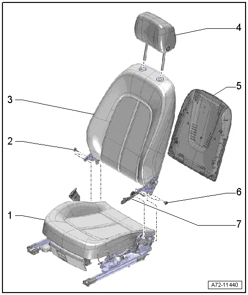
1 - Seat Pan
2 - Bolt
- 33 Nm
- Quantity: 2
- Self-locking
- Replace
- Threaded holes for bolts must be cleaned, for example, with a thread tap
3 - Backrest
- Removing and installing. Refer to → Chapter "Front Backrest, Removing and Installing, Standard/Sport Seat".
4 - Headrest
- Removing and installing. Refer to → Chapter "Headrest, Removing and Installing".
5 - Backrest Cover
- Vehicles with cargo net: the cargo net cannot be separated from the backrest cover.
- Removing and installing. Refer to → Chapter "Backrest Cover, Removing and Installing".
- Attach to the top of the backrest frame and then press on it until it audibly locks
6 - Bolt
- 33 Nm
- Quantity: 2
- Self-locking
- Replace
- Threaded holes for bolts must be cleaned, for example, with a thread tap
7 - Wiring Harness
- From the side airbag to the connector station
- Depending on optional equipment, there may be more wiring harnesses, such as for the backrest heating, lumbar support
Overview - Front Backrest, Passenger Folding Seat
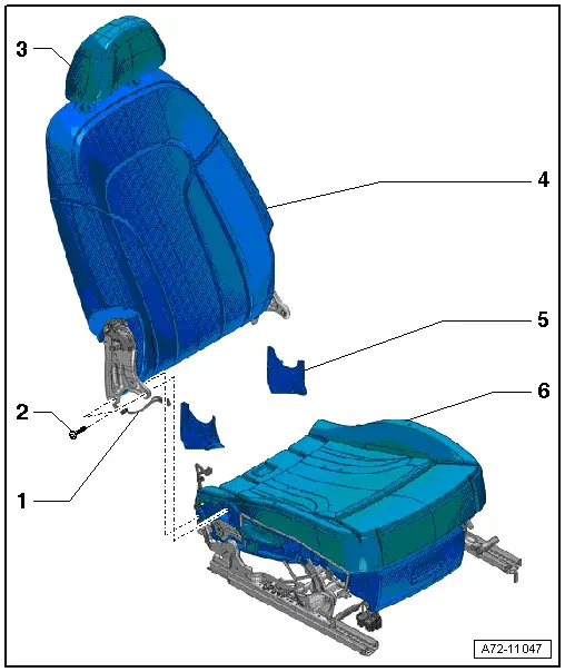
1 - Wiring Harness
- Running from the side airbag to the connector station.
- Depending on optional equipment, there may be more wiring harnesses, such as for seat heating.
2 - Bolts
- 33 Nm
- Quantity: 4
- Self-locking
- Always replace if removed
- Threaded holes for bolts must be cleaned, for example, with a thread tap
3 - Headrest
- Removing and installing. Refer to → Chapter "Headrest, Removing and Installing".
- Must be correctly locked in the headrest guides
4 - Backrest
- Removing and installing. Refer to → Chapter "Backrest, Removing and Installing, Passenger Folding Seat".
5 - Side Backrest Cover
- Removing and installing. Refer to → Chapter "Side Backrest Cover, Removing and Installing".
6 - Seat Pan
Overview - Front Backrest, Spring Mat
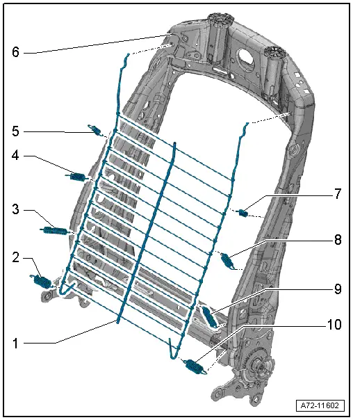
1 - Spring Mat
- Removing and installing. Refer to → Chapter "Spring Mat, Removing and Installing".
- can be removed and installed with and without the pull-springs
2 - Bottom Spring
- Not available individually
3 - Center Spring
- Not available individually
4 - Center Spring
- Not available individually
5 - Top Spring
- Not available individually
6 - Backrest Frame
7 - Top Spring
- Not available individually
8 - Center Spring
- Not available individually
9 - Center Spring
- Not available individually
10 - Bottom Spring
- Not available individually
Overview - Front Backrest, Lumbar Support
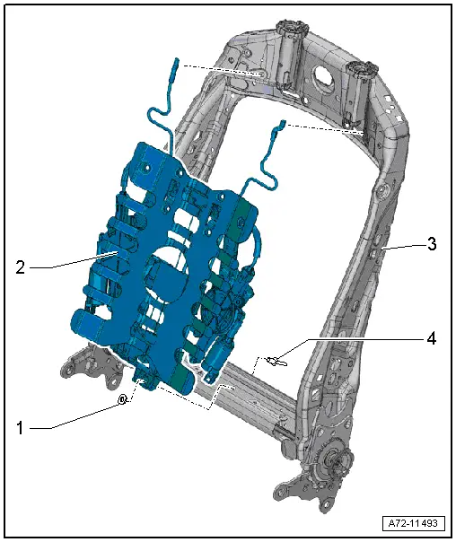
1 - No Replacement Part
- The washer is molded in the lumbar support.
2 - Lumbar Support
- Driver side: with Driver Seat Lumbar Support Curvature Adjustment Motor -V125-/ Driver Seat Lumbar Support Height Adjustment Motor -V129-
- Front passenger side: with Front Passenger Seat Lumbar Support Curvature Adjustment Motor -V126-/ Front Passenger Seat Lumbar Support Height Adjustment Motor -V130-
- Removing and installing. Refer to → Chapter "Lumbar Support Adjustment Motors -V125-/-V126-/-V129-/-V130-, Removing and Installing".
3 - Backrest Frame
4 - Rivet
Overview - Front Backrest, Backrest Adjustment Motor
 Note
Note
The backrest padding and cover are not shown in the illustration.
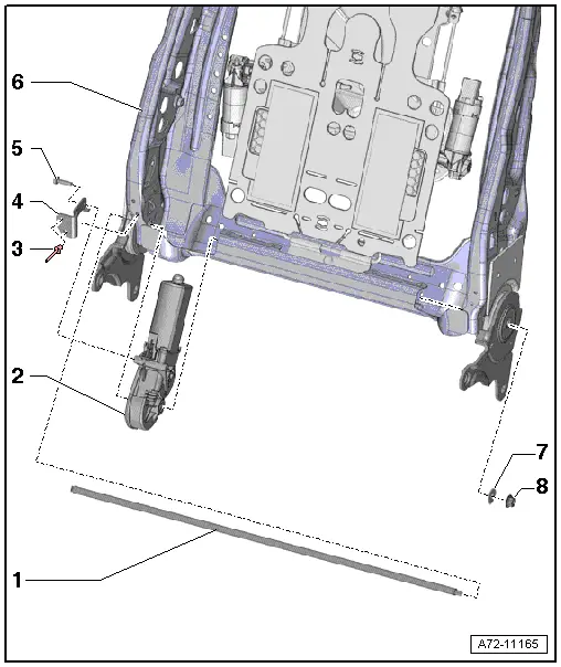
1 - Adjustment Shaft
- The threaded hole for the nut -8- must be cleaned, for example, with a thread tap.
- Coat the threads on the adjustment shaft with locking fluid before installing the nut. Refer to the Parts Catalog.
2 - Driver Backrest Adjustment Motor -V45-
- Front passenger side Front Passenger Backrest Adjustment Motor -V46-
- Removing and installing. Refer to → Chapter "Driver/Front Passenger Backrest Adjustment Motor -V45-/-V46-, Removing and Installing".
3 - Rivet
- Quantity: 2
4 - Bracket
5 - Bolt
- 3.7 Nm
- Replace
- Clean the threaded hole with a thread tap.
- Use locking fluid when installing the bolt. Refer to the Parts Catalog for the locking fluid.
6 - Backrest Frame
7 - Washer
8 - Nut
- 6 Nm
- Replace
Overview - Headrest
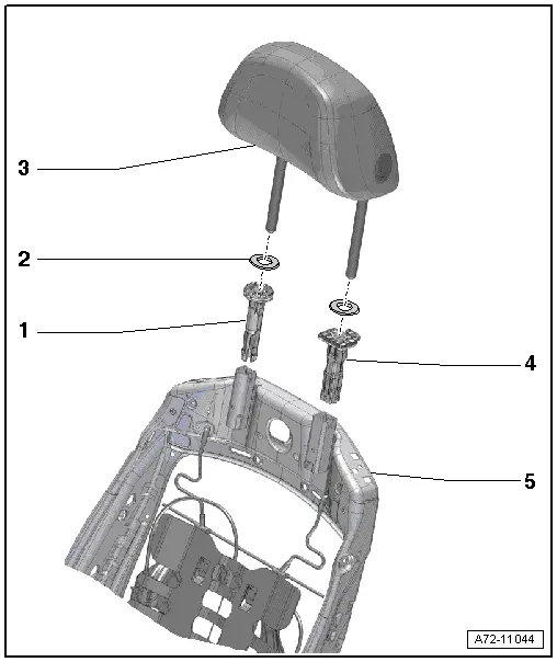
1 - Right Headrest Guide
- Without release button
- Always installed on right side of backrest
- Removing and installing. Refer to → Chapter "Headrest Guide, Removing and Installing".
2 - Cover
- Quantity: 2
- Attached to the backrest cover
3 - Headrest
- Removing and installing. Refer to → Chapter "Headrest, Removing and Installing".
- Must be correctly locked in the headrest guides
4 - Left Headrest Guide
- With release button
- Always installed on left side of backrest
- Removing and installing. Refer to → Chapter "Headrest Guide, Removing and Installing".
5 - Backrest Frame
READ NEXT:
 Overview - Seat Pan
Overview - Seat Pan, Modular Wiring Routing
1 - Corrugated Tube Upper Section
Must terminate flush with the wiring bracket
Must terminate flush with the corrugated tube lower sectio
Overview - Seat Pan, Sill Panel/Tunnel Side Seat Side Trim on Power Front
Seat
1 - Bolt
Quantity: 3
8 Nm
2 - Front Seat
3 - Seat Side Trim on the Tunnel Side
Removing and installing. Refer to
→ Chapter "Seat Side Trim o
Overview - Seat Pan, Drawer
1 - Retaining Tab
2 - Drawer
3 - Bolt
1.5 Nm
4 - Bolt
1.5 Nm
5 - Mount
For the drawer
Removing and installing. Refer to
→&
SEE MORE:
Receiver/Dryer or Accumulator and Restrictor, Replacing after Cleaning
Refrigerant Circuit
Note
Cleaning the refrigerant circuit means flushing it with
refrigerant R134a. Refer to
→ Chapter "Refrigerant Circuit, Cleaning (Flushing), with
Refrigerant R134a" or blowing through with compressed
air and nitrogen. Refer to
→ Chapter "Refrigerant Circuit, Flushi
Name Badges and Emblems
Overview - Name Badges and Emblems
Overview - Name Badges and Emblems, Vehicles through MY 2014
1 - Audi Rings
Removing and installing. Refer to
→ Chapter "Front Emblem, Removing and Installing".
2 - RS Q3-name badge
Equipment level
Removing and installi
