Audi Q3: Overview - Infotainment System
MMI Navigation Plus, 7T6
- Information Electronics Control Module 1 -J794- with DVD player/SD card reader/navigation system integrated in the instrument panel
- Internal hard drive memory (HDD) for storing navigation data and MP3 files
- Integrated control
- Front Information Display Control Head -J685- in center of the instrument panel
- External Audio Source Connection -R199- (AUX IN jack) in the center console storage compartment, UF2
- Radio -R- in the luggage compartment on the left rear side, 8YQ
- Sound systems: Standard/BOSE, 9VD/9VK
Optional
- CD Changer -R41- in the left rear of the luggage compartment, 7A2
- Digital Sound System Control Module -J525- (Sound System BOSE) in the right rear of the luggage compartment under the luggage compartment floor covering.
- Cell phone preparation, 9ZF
- Bluetooth Hands-Free Calling, 9ZX
- Multifunction Steering Wheel
- External Audio Source Connection -R199- (AMI) in the glove compartment, UF7
- AMI online (Wi-Fi), UE2
The MOST bus performs the system data exchange in the MMI.
The connection to other vehicle systems takes place via the Infotainment CAN bus and the Data Bus On Board Diagnostic Interface -J533-.
Perform the Fault Finding with the Vehicle Diagnostic Tester.
Additional information. Refer to Self Study Program "New Data Bus Systems - LIN, MOST Bluetooth".
Notes on MOST bus
The optical Data bus "MOST bus" is used in addition to the CAN bus.
A fiber-optic cable is used as a "connecting cable". Fiber optic cables are routed inside corrugated tubes for protection.
Replace the complete fiber optic cable if possible.
Make sure that the face surfaces of the connectors do not become soiled.
If disconnecting the connectors: Attach the Fiber-Optic Repair Set - Connector Protective Caps -VAS6223/9-.
When routing fiber optic cables, make sure not to go below the minimum bending radius of 25 mm. Do not crush or kink fiber optic cables.
Repairing fiber-optic cables. Refer to → Electrical Equipment General Information; Rep. Gr.97; Fiber-Optic Cable.
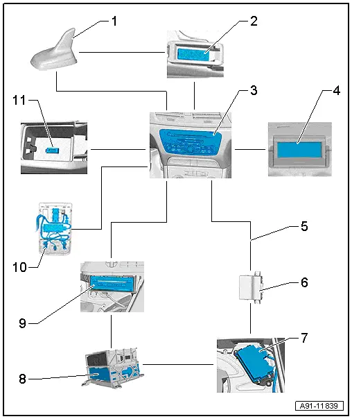
1 - Roof Antenna -R216-
2 - Telephone Baseplate -R126-
- Inside the center console storage compartment
3 - Information Electronics Control Module 1 -J794-
- Inside the instrument panel
4 - Front Information Display Control Head -J685-
- In center of the instrument panel
5 - MOST Bus
6 - Data Bus On Board Diagnostic Interface -J533-
- Behind the driver side left compartment
7 - Digital Sound System Control Module -J525- (Sound System BOSE).
- In the right rear of the luggage compartment under the luggage compartment floor covering
8 - Radio -R-
- Behind the left luggage compartment trim panel
9 - CD Changer -R41-
- Behind the luggage compartment trim panel on the left side.
10 - Microphone Unit in Front Roof Module -R164- (Telephone Microphone -R38-) in the Front Interior Lamp -W1-
11 - External Audio Source Connection -R199- (AMI)
- Inside the center console storage compartment
Component Location Overview - Infotainment System
Component Location Overview - MMI Infotainment
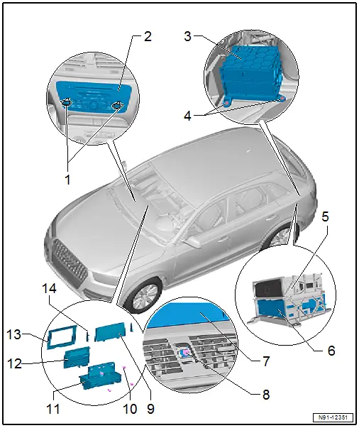
1 - Radio Removal Tool -T10057-
2 - Information Electronics Control Module 1 -J794-
- Connector assignment. Refer to → Chapter "Connector Assignments, MMI Navigation Plus".
- Removing and installing. Refer to → Chapter "Information Electronics Control Module 1 -J794-, Removing and Installing".
3 - Bracket
4 - Nut
- 3 Nm
- Quantity: 3
5 - Bracket
6 - Radio -R-
- Connector assignment. Refer to → Chapter "Radio, Connector Assignment, MMI, 8YQ".
- Removing and installing. Refer to → Chapter "Radio, Removing and Installing, Radio MMI, 8YQ".
7 - Display Support
- Removing and installing. Refer to → Chapter "Infotainment System Display, Removing and Installing".
8 - Bolt
- 3 Nm
9 - Rear Trim
- Clipped to the display support
- Removing and installing. Refer to → Chapter "Infotainment System Display, Removing and Installing".
10 - Bolt
- 2 Nm
- Quantity: 4
11 - Display Support
- Removing and installing. Refer to → Chapter "Infotainment System Display, Removing and Installing".
12 - Front Information Display Control Head -J685-
- Connector assignment. Refer to → Chapter "Front Information Display Control Head -J685-".
- Removing and installing. Refer to → Chapter "Infotainment System Display, Removing and Installing".
13 - Front Trim
- Clipped to Front Information Display Control Head -J685-
- Removing and installing. Refer to → Chapter "Infotainment System Display, Removing and Installing".
14 - Side Trim
- Left and right
- Clipped to rear trim
- Removing and installing. Refer to → Chapter "Infotainment System Display, Removing and Installing".
