Audi Q3: Connector Assignments, MMI Navigation Plus
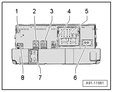
Information Electronics Control Module 1 -J794-
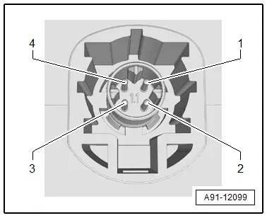
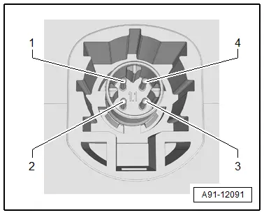
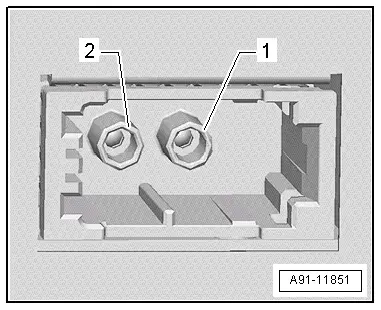
1 - GSM connection from Roof Antenna -R216-
2 - 4-Pin Connector -T4u- to the External Audio Source Connection -R199-/Internet Access Control Module -J666-
3 - 4-Pin Connector -T4al- to the Front Information Display Control Head -J685-
4 - Not Assigned
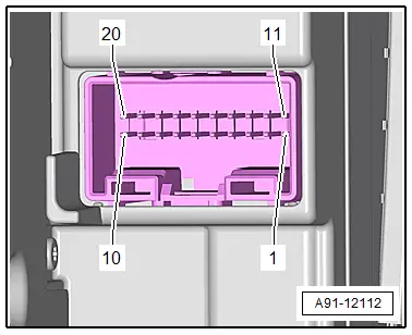
5 - Connection block with four multi-pin connectors
6 - MOST Bus
7 - 20-Pin Connector -T20k- to the Information Electronics Control Module 1 -J794-
8 - GPS connection from the Roof Antenna -R216-
 Note
Note
Unlisted connector terminals are not assigned.
2 - 4-Pin Connector -T4u-
All pins are connected with the External Audio Source Connection -R199-/Internet Access Control Module -J666-.
1 - D (+)
2 - iPod recognized
3 - D (-)
4 - Ground
3 - 4-Pin Connector -T4al-
All pins are connected to the Front Information Display Control Head -J685-.
1 - LVDS (-)
2 - LIN
3 - LVDS (+)
4 - Ground

5 - Connection Block with Four Multi-Pin Connectors
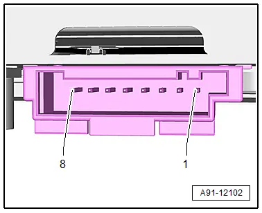
A - 8-Pin Connector -T8ah-
1 - LF mute wire from preliminary setup for cell phone preparation
2 - Power supply to the Information Electronics Control Module 1 -J794-, 20-Pin Connector -T20k-
3 - Wake Up to the Information Electronics Control Module 1 -J794-, 20-Pin Connector -T20k-
4 - Not Assigned
5 - Switch-on signal for the Cellular Telephone Amplifier -R86-
6 - Res MU to the Information Electronics Control Module 1 -J794-, 20-Pin Connector -T20k-
7 - Ring-break Diagnostic Cable

B - 12-Pin Connector -T12x-
21 - CVBS cable (-) for the Rearview Camera System Control Module -J772-
24 - Microphone input (+) from Microphone Unit In Front Roof Module -R164-, Telephone Microphone -R38-
25 - Microphone input (-) from Microphone Unit In Front Roof Module -R164-, Telephone Microphone -R38-
27 - CVBS cable (+) for the Rearview Camera System Control Module -J772-
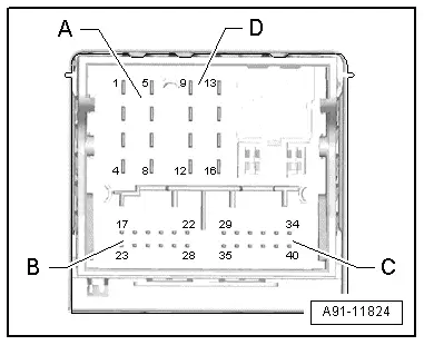
C - 12-Pin Connector -T12k-
All pins are connected to the External Audio Source Connection -R199-.
29 - LF-In Ground
30 - Right LF-In
31 - USB, +5 V. not on the Internet Access Control Module -J666-, UE2
32 - USB, Ground
33 - iPod, ACC Power
34 - Detect, not on the Internet Access Control Module -J666-, UE2
35 - Left LF-In
36 - LF-In ground shielding
37 - CVBS cable (+)
38 - CVBS cable (-)
39 - iPod data
40 - iPod data
Following pins are also still connected with the Internet Access Control Module -J666-, UE2.
31 - USB, +5 V
32 - USB, Ground
34 - Detect

D - 8-Pin Connector -T8ao-
10 - Data from Information Electronics Control Module 1 -J794-, 20-Pin Connector -T20k-
11 - Data to Information Electronics Control Module 1 -J794-, 20-Pin Connector -T20k-
12 - Terminal 31
13 - DIAG signal from Telephone Baseplate -R126-
14 - Res BT from Information Electronics Control Module 1 -J794-, 20-Pin Connector -T20k-
15 - Terminal 30
16 - Ground to Information Electronics Control Module 1 -J794-, 20-Pin Connector -T20k-

6 - MOST bus
1 - Output
2 - Input
7 - 20-Pin Connector -T20k-
6 - Wake UP to the Information Electronics Control Module 1 -J794-
7 - Power supply from the Information Electronics Control Module 1 -J794-
8 - Ground to the Information Electronics Control Module 1 -J794-
13 - Res MU from the Information Electronics Control Module 1 -J794-
14 - Res MU to the Information Electronics Control Module 1 -J794-
15 - Information Electronics Control Module 1 -J794- data
16 - Data from Information Electronics Control Module 1 -J794-
Front Information Display Control Head -J685-
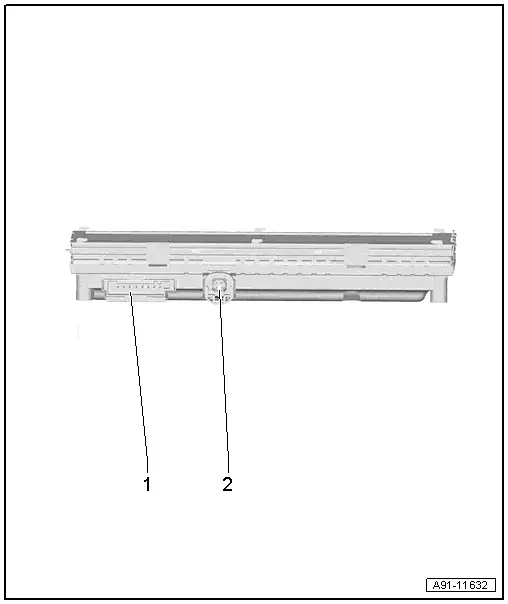
1 - 8-Pin Connector -T8ai-
2 - 4-Pin Connector -T4ao- to the Radio -R-/Information Electronics Control Module 1 -J794-
 Note
Note
Unlisted connector terminals are not assigned.
1 - 8-Pin Connector -T8ai-
4 - Terminal 30
5 - Terminal 31
2 - 4-Pin Connector -T4ao-
All pins are connected to the Radio -R-/Information Electronics Control Module 1 -J794-.
1 - Ground
2 - LVDS (+)
3 - LIN
4 - LVDS (-)