Audi Q3: Overview - Rear Door Trim Panel
Audi Q3 (8U) 2011-2018 Service Manual / Body / Body Interior / Interior Trim / Overview - Rear Door Trim Panel
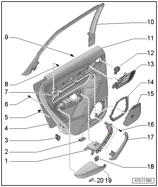
1 - Pull Handle
- With switch mount
- Removing and installing. Refer to → Chapter "Rear Pull Handle, Removing and Installing".
2 - Left Rear Entry Lamp -W33-
- Right: Right Rear Entry Lamp -W34-
- Equipment levels
- Removing and installing. Refer to → Electrical Equipment; Rep. Gr.96; Lamps; Rear Entry Lamp W33/W34 Removing and Installing.
3 - Rear Reflector
- Vehicles with a Left Rear Door Warning Lamp -W37-
- Vehicles with a Right Rear Door Warning Lamp -W38-
- Removing and installing the door warning lamp bulbs. Refer to → Electrical Equipment; Rep. Gr.96; Lamps.
4 - Insulation
5 - Clip
- Quantity: 6 one-piece
- Quantity: 1 two-piece
- Replace any damaged two-piece clips
6 - Bolt
- 1.2 Nm
- For pull handle/armrest
- Quantity: 13
7 - Trim Molding
- The removal and installation is described for the front door and is similar for the rear door. Refer to → Chapter "Trim Molding, Removing and Installing".
- Insert in the door trim panel and press on it until it engages audibly.
8 - Bolt
- For door trim panel
- 2.5 Nm
9 - Bolt
- For inside door release mechanism
- Quantity: 4
- 1.2 Nm
10 - Trim Panel
- For the window frame
- Removing and installing. Refer to → Chapter "Window Frame Trim Panel, Removing and Installing".
11 - Rear Door Trim Panel
- Removing and installing. Refer to → Chapter "Rear Door Trim Panel, Removing and Installing".
12 - Treble Speaker
- Equipment levels
- Removing and Installing. Refer to → Communication; Rep. Gr.91; Sound System; Left/Right Rear Treble Speaker R14/R16 Removing and Installing.
13 - Interior Door Mechanism
- Removing and installing. Refer to → Chapter "Interior Door Mechanism, Removing and Installing".
14 - Frame
- For the speaker trim
- Vehicles with: Speaker Ambient Lighting Bulb 1 -L211-/Speaker Ambient Lighting Bulb 2 -L212-
15 - Speaker Trim
- For bass speaker
- The removal and installation is described for the front door and is similar for the rear door. Refer to → Chapter "Bass Speaker Trim, Removing and Installing".
- Press on until it engages audibly
16 - Bolt
- 2.5 Nm
- For door trim panel
- Quantity: 2
17 - Grip Recess
- for pull handle
- The removal and installation is described for the front door and is similar for the rear door. Refer to → Chapter "Pull Handle Grip Recess, Removing and Installing".
18 - Left Rear Power Window Switch in Left Rear Door -E52-
- Right: Right Rear Window Switch in Right Rear Door -E54-
- Removing and Installing. Refer to → Electrical Equipment; Rep. Gr.96; Controls; Rear Door Controls Component Location Overview.
19 - Armrest
- Removing and installing. Refer to → Chapter "Rear Armrest, Removing and Installing".
20 - Left Rear Door Storage Compartment Illumination Bulb -L170-
- Right: Right Rear Door Storage Compartment Illumination Bulb -L171-
- Removing and installing. Refer to → Electrical Equipment; Rep. Gr.96; Left/Right Rear Door Storage Compartment Illumination Bulb L170/L171 Removing and Installing.
READ NEXT:
 Interior Door Mechanism, Removing and Installing
Removing
- Remove the rear door trim panel. Refer to
→ Chapter "Rear Door Trim Panel, Removing and Installing".
- Remove insulation mat.
- Disconnect and free up the connecto
Component Location Overview - Instrument Panel
1 - Center Console
Overview. Refer to
→ Chapter "Overview - Center Console".
2 - Driver Side Instrument Panel Cover
Overview. Refer to
→ Chapter "Ove
Instrument Panel Side Cover, Removing and Installing
Special tools and workshop equipment
required
Trim Removal Wedge -3409-
Removing
- Pry off the cover -1- for the
instrument panel side cover using the Trim Removal Wedge -3409--arrow-
SEE MORE:
General, Technical data
Safety Precautions
Start/Stop System Safety Precautions
When Working on Vehicles with the Start/Stop System, Observe
the Following:
WARNING
Danger of personal injury because the engine can
start automatically on vehicles with Stop/Start.
When the Start/Stop System is activated
Current Draw Test
WARNING
Do not check or charge a Battery -A- when the visual
indicator has "no color or is
bright yellow". Jump starting must not be used!
There is a risk of explosion during testing,
charging or jump starting.
These Batteries -A- must be replaced.
Make sure the correct charging
© 2019-2025 Copyright www.auq3.net
