Audi Q3: Overview - Telephone
Overview - Telephone, Cell Phone Pre-Installation, 9ZF
Cell Phone Preparation in Information Electronics Control Module 1 -J794-, Concert MOST, 9ZF
The Telephone Baseplate -R126- is installed in the center console. The telephone is operated either by the concert MOST or by the Cellular Telephone -R54-.
The microphones for the Microphone Unit In Front Roof Module -R164- are integrated in the Front Interior Lamp -W1-. One microphone (Telephone Microphone -R38-) is directly connected with the Information Electronics Control Module 1 -J794-.
The connection for the antenna is located on the Telephone Baseplate -R126-.
Cell Phone Preparation in Information Electronics Control Module 1 -J794-, MMI MOST, 9ZF
The Telephone Baseplate -R126- is installed in the center console. The telephone is operated either by the Infotainment system MMI or by the Cellular Telephone -R54-.
The microphones for the Microphone Unit In Front Roof Module -R164- are integrated in the Front Interior Lamp -W1-. One microphone (Telephone Microphone -R38-) is directly connected with the Information Electronics Control Module 1 -J794-.
The connection for the antenna is located on the Telephone Baseplate -R126-.
Perform the Fault Finding with the Vehicle Diagnostic Tester.
Repairing the antenna wires. Refer to → Electrical Equipment General Information; Rep. Gr.97; Antenna Wires, Repairing.
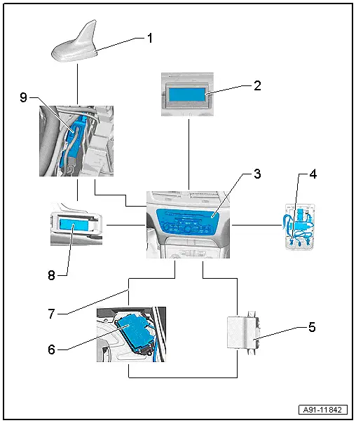
1 - Roof Antenna -R216-
2 - Front Information Display Control Head -J685-
- In center of the instrument panel
3 - Information Electronics Control Module 1 -J794-
- Inside the instrument panel
4 - Microphone Unit in Front Roof Module -R164- (Telephone Microphone -R38-)
- In the Front Interior Lamp -W1-
5 - Data Bus On Board Diagnostic Interface -J533-
- Behind the driver side left compartment
6 - Digital Sound System Control Module -J525-
- In the right rear of the luggage compartment under the luggage compartment.
7 - MOST Bus
8 - Telephone Baseplate -R126- with Cellular Telephone -R54-
9 - Cellular Telephone Amplifier -R86-
- Behind the Right Luggage Compartment Trim Panel
Overview - Telephone, Cell Phone Preparation Preliminary Setup
- The preliminary setup connector is located under the storage bin in the center console.
- The microphones for the Microphone Unit In Front Roof Module -R164- are integrated in the Front Interior Lamp -W1-. A microphone (Telephone Microphone -R38-) is connected to the connector.
- The antenna connection from the Telephone Antenna -R65- is located on the connector.
Cell Phone Preparation Preliminary Setup
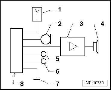
1 - Roof Antenna -R216-
2 - Microphone Unit in Front Roof Module -R164- (Telephone Microphone -R38-) in the Front Interior Lamp -W1-
3 - Radio -R-
4 - Sound Systems
5 - Terminal 15
6 - Terminal 30
7 - Terminal 31
8 - 18-Pin Multi-Pin Connector, in the Center Console
Overview - Telephone, Bluetooth Hands-Free Calling, 9ZX
Bluetooth Hands-Free Calling in the Information Electronics Control Module 1 -J794-, Concert MOST, 9ZX
- The Information Electronics Control Module 1 -J794- is installed with the Microphone Unit In Front Roof Module -R164- and is part of the hands-free setup. The connection to the Cellular Telephone -R54- takes place via Bluetooth.
- The Bluetooth Antenna -R152- is integrated in the Information Electronics Control Module 1 -J794-.
Bluetooth Hands-Free Calling in the Information Electronics Control Module 1 -J794-, MMI MOST, 9ZX
- The Information Electronics Control Module 1 -J794- is installed with the Microphone Unit In Front Roof Module -R164- and is part of the hands-free setup. The connection to the Cellular Telephone -R54- takes place via Bluetooth.
- The Bluetooth Antenna -R152- is integrated in the Information Electronics Control Module 1 -J794-.
Perform the Fault Finding with the Vehicle Diagnostic Tester.
Repairing the antenna wires. Refer to → Electrical Equipment General Information; Rep. Gr.97; Antenna Wires, Repairing.
Notes on Bluetooth Technology
- A standardized radio connection is used to transfer data between the Information Electronics Control Module 1 -J794- and Cellular Telephone -R54- - Bluetooth Technology.
- An additional transmitter/receiver unit is installed in the Information Electronics Control Module 1 -J794-. A Bluetooth Antenna -R152- connects the Information Electronics Control Module 1 -J794- and the Cellular Telephone -R54- so that the Cellular Telephone -R54- can be operated without a wire connection.
- The range of the radio connection is approximately 10 m.
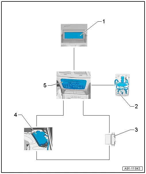
1 - Front Information Display Control Head -J685-
- In center of the instrument panel
2 - Microphone Unit in Front Roof Module -R164- (Telephone Microphone -R38-)
- In the Front Interior Lamp -W1-
3 - Data Bus On Board Diagnostic Interface -J533-
- Behind the driver side left compartment
4 - Digital Sound System Control Module -J525-
- In the right rear of the luggage compartment under the luggage compartment.
5 - Information Electronics Control Module 1 -J794- with Bluetooth Antenna -R152-
- Inside the instrument panel
Component Location Overview - Telephone System
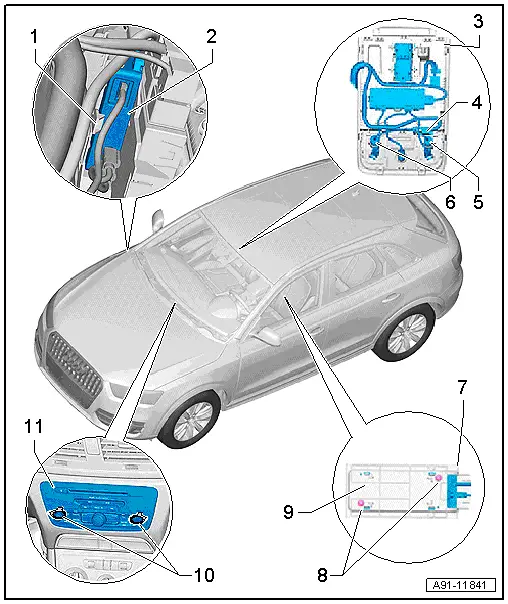
1 - Bracket Catch
2 - Cellular Telephone Amplifier -R86-
- Connector assignment. Refer to → Chapter "Cellular Telephone Amplifier -R86-, Connector Assignment".
- Removing and installing. Refer to → Chapter "Cellular Telephone Amplifier -R86-, Removing and Installing".
3 - Front Interior Lamp -W1-
- Overview. Refer to → Chapter "Overview - Microphone Unit".
4 - 4-Pin Connector -T4bg-
5 - Telephone Microphone -R38-
- Component location overview. Refer to → Chapter "Overview - Microphone Unit".
- Connector assignment. Refer to → Chapter "Connector Assignment, Microphone Unit".
- Removing and installing. Refer to → Chapter "Microphone Unit in Front Roof Module -R164-, Removing and Installing".
6 - Interior Microphone -R74-
- Component location overview. Refer to → Chapter "Overview - Microphone Unit".
- Connector assignment. Refer to → Chapter "Connector Assignment, Microphone Unit".
- Removing and installing. Refer to → Chapter "Microphone Unit in Front Roof Module -R164-, Removing and Installing".
7 - Telephone Baseplate -R126-
- Circuit board bolts: 1 Nm
- Removing and installing. Refer to → Chapter "Telephone Baseplate -R126-, Removing and Installing".
8 - Bolt
- 1 Nm
- For the base plate
- Quantity: 2
9 - Base plate
10 - Radio Removal Tool -T10057-
11 - Information Electronics Control Module 1 -J794-, Concert/MMI MOST
- Cell phone preparation connector assignment concert MOST. Refer to → Chapter "Connector Assignments, Cell Phone Preparation Concert MOST, 9ZF".
- Pin assignment, cell phone preparation, MMI. Refer to → Chapter "Connector Assignments, Cell Phone Preparation MMI, 9ZF"
- BT-hands-free calling connector assignment concert MOST. Refer to → Chapter "Connector Assignment, Bluetooth Hands-Free Calling Concert MOST, 9ZX".
- BT-hands-free calling connector assignment MMI. Refer to → Chapter "MMI Bluetooth Hands-Free Calling Connector Assignments, 9ZX".
- Removing and installing. Refer to → Chapter "Information Electronics Control Module 1 -J794-, Removing and Installing".
READ NEXT:
 Overview - Microphone Unit
The Microphone Unit In Front Roof Module -R164- is installed
in the Front Interior Lamp -W1-. Up to three microphones may be
installed, depending on the equipment.
One microphone (Interior Microp
Connector Assignments, Cell Phone Preparation Concert MOST, 9ZF
Information Electronics Control Module 1 -J794-
1 - Connector AM/FM1 from the Antenna Amplifier -R24- (Radio
Antenna 2 -R93-)
2 - DAB connection from Antenna Amplifier 4 -R113-
Connector Assignments, Cell Phone Preparation MMI, 9ZF
Information Electronics Control Module 1 -J794-
1 - Not Assigned
2 - 4-Pin Connector -T4u- to the External Audio Source
Connection -R199-/Internet Access Control Mo
SEE MORE:
Sunroof Frame, Removing and Installing
1 - Bolt
3 Nm
2 - Power Sunroof Control Module -J245-.
Performing the adaptation procedure. Refer to
→ Chapter "Motor Adaptation".
3 - Bolt
8 Nm.
4 - Roof
5 - Panorama Roof Frame
Removing
Headliner remo
General, Technical data
Repair Information
Wire Routing and Securing
When loosening or removing and installing hydraulic, pneumatic or electrical
lines, draw sketches or take pictures. This will ensure they are installed in
their original positions.
Contact Corrosion
Contact corrosion can occur if incorrect fastene
