Audi Q3: Radio Installation Instructions
Retrofitting Radio Systems
General Information
Before installing radios and telephone systems (radio systems), disconnect the negative terminal of the Battery -A-. Refer to →Electrical Equipment; Rep. Gr.27.
Use the applicable wiring diagrams. Refer to → Wiring diagrams, Troubleshooting & Component locations.
Secure wiring harnesses to cable ties. Wrap connector couplings with foam to prevent rattling.
Follow the manufacturer operating and installation instructions for cell phones, radios and antennas. Refer to Operating Instructions.
- Battery -A-, Disconnecting and Connecting. Refer to →Electrical Equipment; Rep. Gr.27.
- Wiring diagrams, fuse assignment and component locations. Refer to → Wiring diagrams, Troubleshooting & Component locations.
- Trim Panels, Removing and Installing. Refer to →Body Interior; Rep. Gr.70.
- Standard Devices, Removing and Installing. Refer to →Communication; Rep. Gr.91.
- Antenna Wires, Repairing. Refer to → Electrical Equipment General Information; Rep. Gr.97; Wiring Harness and Connectors, Repairing; Antenna Wires, Repairing.
- Wiring Harnesses, Repairing. Refer to → Electrical Equipment General Information; Rep. Gr.97; Wiring Harness and Connectors, Repairing.
Transmitting Power and Possible Component Locations
Audi permits the installation and operation of radio systems, as long as the transmitting power at the antenna base (listed in the tables for the respective vehicle model) is not exceeded. For required antenna component locations and transmitting powers, refer to the tables. Refer to → Chapter "A1 from MY 2011 through MY 2012".
The limits set forth in VDE 0848 Part 2 (maximum permissible field intensity to protect persons) must also be maintained even through reduction of transmission output.
Power Supply
When retrofitting radio systems in the vehicle, the Battery -A- is used to connect the positive and negative wires.
The wiring harness must also be made:
- Positive wire: 2.5 mm strong red wire
- Negative wire: 2.5 mm strong brown wire
- Terminal 15 wire: 1.5 mm strong black wire
The positive wire should be equipped with a fuse next to Battery -A-. Attach a fuse panel next to the Battery -A- for this. Cover the positive and negative wires with an insulating hose. Attach the appropriate cable shoes on the battery side. Proceed according to the radio system operating instructions on the device side. Refer to Operating Instructions.
Route the additional wiring harness separately from the vehicle wiring (distance greater than 10 cm).
 Note
Note
Crossing the standard wiring is better than routing it parallel.
Antenna and Wiring
A shielded wire must be used between the radio and the antenna. Shielding must be grounded on the device side and antenna side. At the same time, there must be a proper and stable ground connection for the antenna base wire to the vehicle body.
The transmitting system must only be used when shielded to avoid sheath waves in antenna wiring. To ensure the radio system is tuned and operating correctly, an output/performance test is recommended.
It is only possible to have "on glass" antennas on vehicles without tinted glass.
Other Auxiliary Installations
The installation of other electronic equipment such as business equipment (TV, FAX) or household equipment (electrical cooling box) is only permitted if these devices are marked with a CE or e-sign. Power must be supplied by a separate wiring harness equipped with a fuse.
Overview - Battery -A-/Radio/Fuses/Wiring Harnesses
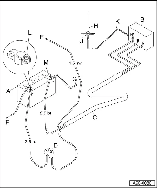
A - Battery -A-
- Installation position, Disconnecting. Refer to →Electrical Equipment; Rep. Gr.27.
B - Radio, Telephone
- Installation position, Removing and Installing. Refer to →Communication; Rep. Gr.91.
C - Wiring Harness
- Must be made
- Positive wire (terminal 30) 2.5 diameter, red
- Ground wire (terminal 31) 2.5 diameter, brown
- Positive wire (terminal 15a) 1.5 diameter, black
D - Fuse Panel
- Next to the Battery -A-
E - Terminal 15a
- Always clipped on terminal 15a output
- Wire must be protected
- Fuse maximum 15 A
F - To the Starter -B-
- Standard wire
G - Body Ground
- Directly next to the Battery -A-
H - Transmitting/Receiving Antenna
- For required antenna component locations and transmitting powers, refer to the tables. Refer to → Chapter "A1 from MY 2011 through MY 2012".
J - Antenna Ground
- Proper and durable connection/corrosion protection
K - Shielded Antenna Wire
- Wire with coaxial connector
L - Positive Connection
- Secure red wire with cable shoe A6-2.5 under the nut
- If possible, route wiring harness separately
M - Negative Wire
- Secure brown wire with cable shoe A6-2.5 under the nut
- If possible, route wiring harness separately
Transmitter Power Output and Antenna Component Locations
Q3 from MY 2015
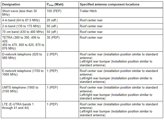
eff. = effective transmission output
PEP = maximum carrier power (Peak Envelope Power)
 WARNING
If radio systems are installed with a higher output or with an antenna that differs from the items named above, the vehicle operating permit may be void.
Revision History
DRUCK NUMBER: A005A602821

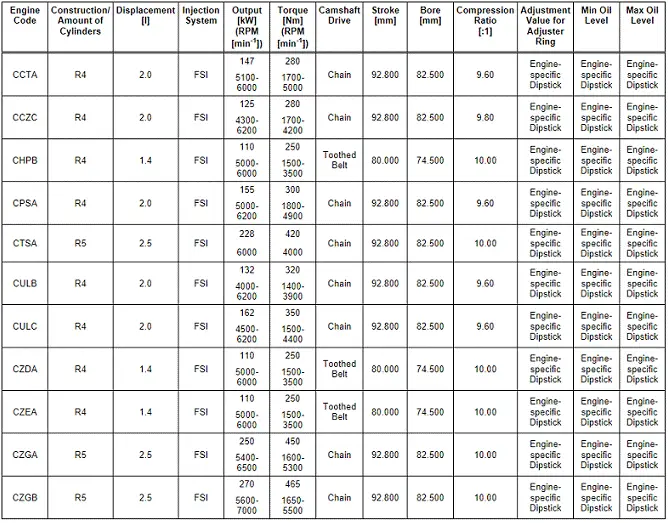
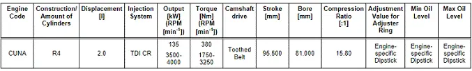
Engine
Oil Gauge Tester T40178 Service Values
General, Technical data
Engine Overview with Adjustment Values, Gauge - Oil Gauge Tester (T40178)
Audi Q3 - Model Code 8U
Gasoline Engines
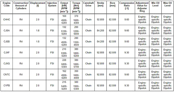
Audi TT - Model Code FV
Gasoline Engines
Diesel Engines
READ NEXT:
SEE MORE:
 Trailer Hitch
Overview - Trailer Hitch Socket and Towing Recognition Control Module
1 - LED Indicator Lamp
Trailer Hitch -Locked- Indicator Lamp -K226-, Trailer Hitch
-Unlocked- Indicator Lamp -K227-
Make sure the trailer hitch is locked correctly
Removing and installing. Refer to
→&nbs
Towing Guide
Towing Guide
Note
This is a "guide" for Audi models and their towing weights.
The proper towing weight of the respective vehicle must
always adhere to the corresponding vehicle document (certificate
of conformity).
For the towing weights of individual models and special
model
