Audi Q3: Trailer Hitch
Overview - Trailer Hitch Socket and Towing Recognition Control Module
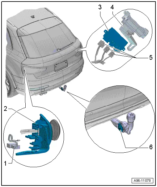
1 - LED Indicator Lamp
- Trailer Hitch -Locked- Indicator Lamp -K226-, Trailer Hitch -Unlocked- Indicator Lamp -K227-
- Make sure the trailer hitch is locked correctly
- Removing and installing. Refer to → Chapter "LED Indicator Lamp, Removing and Installing".
2 - Mount
- For the cable
- For unlocking the trailer hitch
3 - Towing Recognition Control Module -J345-
- Removing and installing. Refer to → Chapter "Towing Recognition Control Module -J345-, Removing and Installing".
4 - Frame
- For Towing Recognition Control Module -J345-
5 - Connectors
6 - Trailer Socket -U10-
- Removing and Installing. Refer to → Electrical Equipment General Information; Rep. Gr.96; Trailer Hitch.
- For the connector assignment. Refer to → Electrical Equipment General Information; Rep. Gr.96; Trailer Hitch.
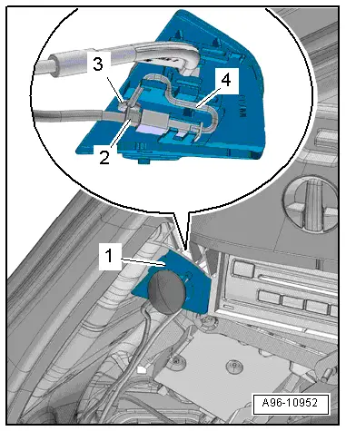
LED Indicator Lamp, Removing and Installing
Removing
- Remove the luggage compartment left side trim panel cover.
- Disconnect the connector -2-.
- Remove the LED indicator lamp -3- from the cable mount -1- and free up the electric wire -4-.
Installing
Install in reverse order of removal.
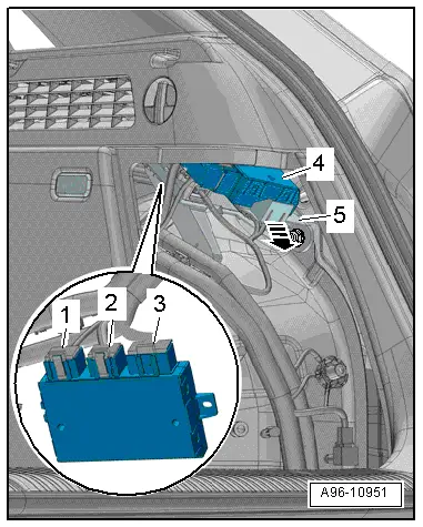
Towing Recognition Control Module -J345-, Removing and Installing
- If replacing the control module, select the "Replace Control Module" function see Vehicle Diagnostic Tester.
Removing
- Remove the luggage compartment right side trim panel cover.
- Open the clip -arrow-.
- Remove the control module -4- from the frame.
- Disconnect the connectors -1, 2 and 3-.
Installing
Install in reverse order of removal.
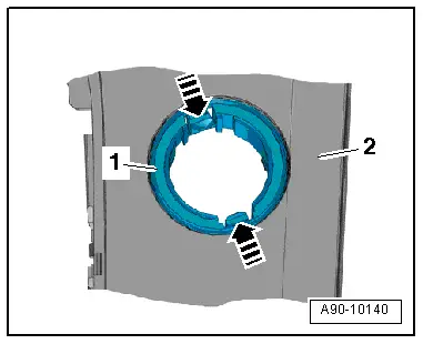
- Remove the illumination ring -1- with the Socket Illumination Bulb -L42- from the center console rear cover -2-.
Installing
Install in reverse order of removal. Note the following:
- The illumination ring can only be inserted into the mount in one position.
- Install the 12 V socket. Refer to → Chapter "12 V Socket 2 -U18-, Removing and Installing".
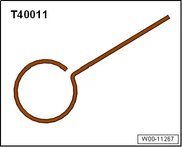
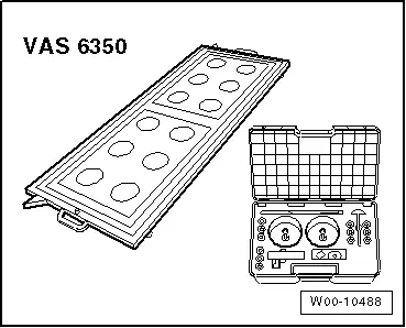
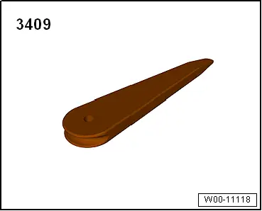
Special Tools
Locking Pin -T40011-
Calibration Tool -VAS6350-
Trim Removal Wedge -3409-
READ NEXT:
 Component Location Overview - Relay Carriers, Fuse Panels and E-Boxes
Overview - E-box, Wire Junction, Fuse Panel, Suppressor
1 - Nut
9 Nm
2 - Wiring Harness
3 - Nut
4.5 Nm
4 - Suppressor -C24-
Removing and i
E-Box, Removing and Installing
Removing
- Remove the relay and fuse panel and move them to the side
with the wires still connected. Refer to
→ Chapter "Relay and Fuse Panel B -SB- in the E-Box, Removing
and Insta
SEE MORE:
Air Distribution Housing, Removing and Installing
Removing
- Remove the Air Conditioning (A/C) unit (heater). Refer to
→ Chapter "Heater and A/C Unit, Removing and Installing".
- Remove the bolts -arrows-.
- Remove the heater core cover -1-.
- Remove the bolts -A-.
- Remove the clamps -B-.
- Remove the
A/C Compressor Regulator Valve -N280-, Checking Switch-On Signal
Special tools and workshop equipment
required
Vehicle Diagnostic Tester
Connector Test Set -VAG1594D-
Probe -VAS5051/8-
Test Sequence
- Remove the noise insulation. Refer to
→ Body Exterior; Rep. Gr.66; Noise Insulation; Noise Insulation,
Removing and Installi
