Audi Q3: Vehicle Diagnosis, Testing and Information Systems
 WARNING
- During road tests using a vehicle diagnostic and information system, there is the hazard of extreme to lethal injuries!
- If vehicle diagnostic and information system is deposited in the action area of an airbag during a road test, here is the hazard of extreme to lethal injuries in the event the airbag deploys!
- During road tests, have a person sitting in the rear seat to operate the vehicle diagnostic and information system.
Audi TT and Audi R8
 WARNING
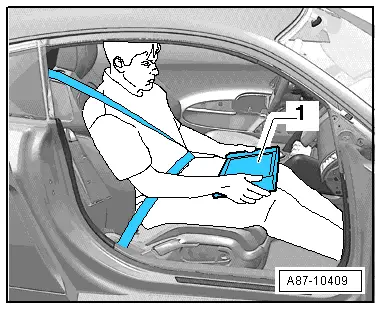
- During road tests using a Vehicle Diagnostic Tester, there is the hazard of extreme to lethal injuries!
- If vehicle diagnostic and information system is deposited in the action area of an airbag during a road test, here is the hazard of extreme to lethal injuries in the event the airbag deploys!
- During road tests, have a person sitting in the front passenger seat in the rearmost position to operate the Vehicle Diagnostic Tester.
- The Vehicle Diagnostic Tester-1- must lie flat on the passenger's legs and be operated by that person, as shown in the illustration.
- Connect the Vehicle Diagnostic Tester. Refer to → Chapter "Vehicle Diagnostic Tester, Connecting".
Vehicle Diagnostic Tester, Connecting
Special tools and workshop equipment required
- Vehicle Diagnostic Tester and diagnostic cable
Procedure
- Engage the parking brake or operate the electromechanical parking brake.
- Shift the shifter lever into neutral or place the selector lever in the "P" position.
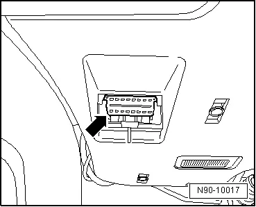
- Turn off the ignition and connect the Vehicle Diagnostic Tester to the Data Link Connector (DLC) with the diagnostic cable -arrow-.
- When using the Remote Diagnosis Head -VAS5054A- or the Diagnosis Interface -VAS5055- pay attention to the Operating Instructions.
- Turn on the ignition.
- Turn off all electrical consumers.
 Note
Note
If a error message appears on the screen of the Vehicle Diagnostic Tester. Refer to the Operating Instructions.
READ NEXT:
 Vehicle Electrical System, General Repair Information
Caution
When disconnecting and connecting battery, the
procedure must be followed as described in the Repair
Manual.
WARNING
Some tools are supplied with a tool safety clip,
Wiring Harness Repair Set
Wiring Harness Repair Set -VAS1978-
The Wiring Harness Repair Set -VAS1978- makes optimal repair
quality possible in the realm of vehicle electronics. Using the
tools, repairs affecting harness c
Tool Descriptions
Crimping Pliers with Insert
The Crimping Pliers without Insert -VAS1978/1- with Crimping
Pliers - Insert 2 -VAS1978/2- is a component of the Wiring
Harness Repair Set -VAS1978- and is used to criSEE MORE:
Opening navigation
Applies to: vehicles with navigation system
Fig. 128 Route guidance not started
The navigation system directs you to your destination,
around traffic incidents, and on alternative
routes, if desired.
Opening navigation
Applies to: MMI: Press NAVIGATION on the
home screen.
After accessing the na
Center Console Rear Trim, Removing and Installing
Special tools and workshop equipment
required
Wedge Set -T10383-
Removing
- Move the front seats all the way forward.
Vehicles with a Center Armrest:
- Vehicles with vents: remove the rear vent. Refer to
→ Chapter "Rear Vents, Removing and Installing".
- Equipment