Audi Q3: Cooling Output, Checking
Cooling Output, Checking
Special tools and workshop equipment required
- Vehicle Diagnostic Tester
- A standard thermometer (for temperature measurements, if necessary a thermometer with two measuring probes for simultaneous measurement, for example, for temperature on the right and left)
 Note
Note
- With the Start/Stop System, the stop function is disabled depending on the setting on the A/C Control Module -J301- (for example, the heater is on). As soon as there is a request for heating, the engine is started. In cooling mode, the A/C Control Module -J301- does not limit the stop function. Refer to Vehicle Diagnostic Tester in the "Guided Fault Finding" function.
- With the Start/Stop Function, the stop function is disabled depending on the setting on the Climatronic Control Module -J255- control head. If, for example, "Defrost" mode is selected, the stop function is not possible or is cancelled and the engine is started as soon as this mode is selected. The same applies in the case of heating and cooling. The difference between the target and actual temperature is greater than a specified value. Refer to Vehicle Diagnostic Tester in the "Guided Fault Finding" function.
A/C Cooling Output, Testing Requirements
- The ambient temperature is greater than 15 ºC (60 ºF).
- Radiator and condenser are clean (if necessary, clean).
- The ribbed belt, which drives the Air Conditioning (A/C) compressor, is OK and is tensioned correctly. The belt pulley is actually driving the A/C compressor. Refer to → Chapter "Overview - Belt Pulley".
- All air ducts, covers and seals are OK and properly installed.
- Air flow through dust and pollen filter not obstructed by dirt. Refer to → Chapter "Dust and Pollen Filter, Removing and Installing".
- The air intake of the A/C unit (in fresh air and recirculating air mode) is not impaired by soiling or components installed as retrofit.
- For the glove compartment cooling, the air guide to the glove compartment cooling is installed as specified (without glove compartment cooling, the connection for it is sealed). Refer to → Chapter "Air Guide for Glove Compartment Cooling, Removing and Installing".
- The vehicle is not exposed to sunlight.
- The engine is warm (the coolant temperature is higher than 80 ºC (176 ºF) ).
- The Diagnostic Trouble Code (DTC) memory for the Climatronic Control Module -J255-/A/C Control Module -J301- control head was checked and erased, the basic setting was performed and the Climatronic Control Module -J255- coding was checked on the Vehicle Diagnostic Tester in the "Guided Fault Finding" function.
- The adaption for the Climatronic Control Module -J255- was checked. Refer to Vehicle Diagnostic Tester in the "Guided Fault Finding".
- All instrument panel vents and, if equipped, the vents in the rear center console are opened.
- The vent for glove compartment cooling (in the glove compartment) is closed for the glove compartment cooling.
- Ensure that the air outlet from the rear footwell vents (under the front seats) is not blocked by floor mats or other objects.
- The hood is closed.
- The engine is running.
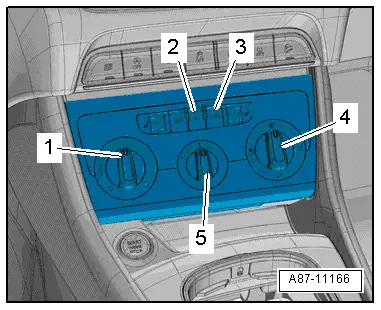
Adjust the following settings on the A/C Control Module -J301- control head:
- Turn the temperature knob -1- to the "cold" stop.
- The A/C compressor is on - the indicator lamp in the AC or A/C button -2- illuminates.
- The recirculating air mode is on - the indicator lamp in the recirculation button -3- illuminates.
- Turn the knob -5- for the fresh air blower to level "4".

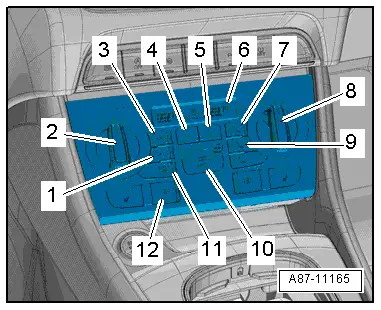
Adjust the following settings on the Climatronic Control Module -J255- control head:
- "Auto" mode - the indicator lamp in the AUTO button -10- illuminates.
- Temperature preset "cold" via the knobs -2 and 8- - "LO" for the driver and front passenger side in the display -6- on the Climatronic Control Module -J255-.
- The A/C compressor is on - the indicator lamp in the AC or A/C button -1- illuminates.
- Preselect for the fresh air blower -5-"maximum speed" - in the display on the Climatronic Control Module -J255-.
 Note
Note
- The indicator lamps in the AUTO buttons go out when the fresh air blower speed is changed manually.
- The maximum possible fresh air blower speed depends on several conditions (vehicle voltage, etc.)
Functions with Engine Running:
- The coolant fan(s) (Coolant Fan -V7- and Coolant Fan 2 -V177-) run (activation and speed depend on refrigerant circuit pressure and engine temperature).
 Note
Note
- Depending on the version of the Climatronic Control Module -J255- control head, the coolant fan(s) (Coolant Fan -V7- and Coolant Fan 2 -V177-) are only switched on at a certain refrigerant circuit pressure (currently at a pressure of approximately 9 bar). The activation of the coolant fan(s) is displayed in the "read measured value" function. Refer to Vehicle Diagnostic Tester in the "Guided Fault Finding" Function.
- Depending on the engine control module, the target and the actual speed of the Coolant Fans -V7- and Coolant Fan 2 -V177- can vary from one another. Refer to Vehicle Diagnostic Tester in the "Guided Fault Finding" function.
- The fresh air blower runs at maximum speed.
 Note
Note
The maximum possible fresh air blower speed depends on several conditions (vehicle voltage, etc.)
- The A/C system goes in recirculating air mode (approximately one minute after starting the engine, the back pressure/fresh air door is closed and the air recirculation door is opened. The fresh air blower extracts the air from passenger compartment below instrument panel / behind the glove compartment).
If one of these requirements is not met:
- Check the DTC memory, perform an output diagnostic test and read the measured values. Refer to Vehicle Diagnostic Tester in the "Guided Fault Finding" function.


