Audi Q3: Instrument Cluster
Overview - Instrument Cluster
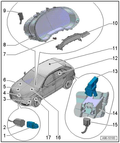
1 - Outside Air Temperature Sensor -G17-
- Removing and installing. Refer to → Chapter "Outside Air Temperature Sensor, Removing and Installing".
2 - Connector
- For Outside Air Temperature Sensor -G17-
3 - Windshield Washer Fluid Level Sensor -G33-
- Removing and installing. Refer to → Chapter "Windshield Washer Fluid Level Sensor, Removing and Installing".
4 - Oil Level Thermal Sensor -G266-
- Removing and installing. Refer to → Rep. Gr.17; Oil Pan/Oil Pump; Oil Level Thermal SensorG266, Removing and Installing.
5 - Oil Pressure Switch
- Removing and installing. Refer to → Rep. Gr.17; Oil Filter/Oil Pressure Switch.
6 - Engine Coolant Level Warning Switch -F66-
7 - Bolt
- 3 Nm
- Quantity: 2
8 - Instrument Cluster
- With Instrument Cluster Control Module -J285-
- Removing and installing. Refer to → Chapter "Instrument Cluster with Instrument Cluster Control Module -J285-, Removing and Installing".
- Multi-pin connector pin assignment. Refer to → Chapter "Instrument Cluster Multi-Pin Connector Contact Assignment".
9 - Connector
- For instrument cluster
10 - Gap Cover
- Removing and Installing. Refer to → Body Interior; Rep. Gr.68; Storage Compartments/Covers; Instrument Cluster Gap Cover, Removing and Installing.
11 - Fuel Level Sensor -G-
- Connector assignment. Refer to → Chapter "Fuel Level Sensor -G- Connector Assignment".
- Removing and Installing. Refer to → Rep. Gr.20; Fuel Delivery Unit/Fuel Level Sensor; Fuel Level SensorG Removing and Installing.
12 - Fuel Level Sensor 2 -G169-
- Connector assignment. Refer to → Chapter "Fuel Level Sensor 2 -G169- Connector Assignment".
- Removing and installing. Refer to → Fuel Supply System; Rep. Gr.20; Fuel Delivery Unit/Fuel Level Sensor; Fuel Level Sensor 2G169, Removing and Installing
13 - Radio Frequency Controlled Clock Receiver -J489-
- Removing and installing. Refer to → Chapter "Radio Frequency Controlled Clock Receiver, Removing and Installing".
14 - Mount
- Integrated in the bumper cover
15 - Connector
- For Radio Frequency Controlled Clock Receiver -J489-
16 - Brake Fluid Level Warning Switch -F34-
- Removing and Installing. Refer to → Break System; Rep. Gr.47; Overview - Brake Booster/Brake Master Cylinder.
17 - Left Front Brake Pad Wear Sensor -G34-
- Removing and installing. Refer to → Brake System; Rep. Gr.46; Front Brakes; Brake Pads, Removing and Installing.
Instrument Cluster with Instrument Cluster Control Module -J285-, Removing and Installing
Special tools and workshop equipment required
- Hook Tool -T40207-
 Note
Note
- All warning lamps in instrument cluster are fitted with light-emitting diodes. Instrument cluster must be replaced in the event of warning lamp failure.
- Do not disassemble the instrument cluster.
- It is not necessary to remove the steering wheel in order to remove the instrument cluster.
- If replacing the control module, select the "Replace Control Module" function Vehicle Diagnostic Tester.
Removing
- Adjust steering wheel downward and to rear as far as possible, use entire adjustment range of steering column adjustment for this.
- Turn off the ignition.
- Vehicles with ignition lock: Remove the key.
- Remove the gap cover and place on the upper steering column trim panel. Refer to → Body Interior; Rep. Gr.68; Storage Compartments/Covers; Instrument Cluster Gap Cover, Removing and Installing.
- Remove the bolts -4 and 5-.
- Guide the Hook Tool -T40207- carefully between the instrument panel -2- and the instrument cluster -1- and engage from behind in the pull tab -3-.
- Pull the instrument cluster out just far enough until it is touching the steering wheel.
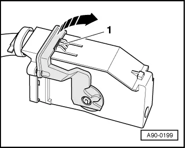
- Disconnect the connector.
- To disconnect the connector, press the tab -1-, turn the retaining bracket in direction of -arrow- and remove the connector.
- Remove the instrument cluster on the driver side between the steering wheel and the instrument panel.
Installing
Install in reverse order of removal. Note the following:
- Follow the instructions on the Vehicle Diagnostic Tester display with a new instrument cluster.
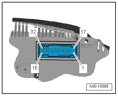
Instrument Cluster Multi-Pin Connector Contact Assignment
32-Pin Connector, Gray
1 - Fuel Level Sensor -G- - full
2 - Fuel Level Sensor -G- - empty
3 - Fuel Level Sensor 2 -G169- - full
4 - Fuel Level Sensor 2 -G169- - empty
5 - Radio controlled clock signal
6 - Radio Frequency Controlled Clock 5 V
7 - Transponder 1
8 - Transponder 2
9 - Not Assigned
10 - Not Assigned
11 - Oil Level Thermal Sensor -G266-
12 - Not Assigned
13 - Not Assigned
14 - Not Assigned
15 - Brake pad
16 - Terminal 31
17 - Windshield Washer Fluid Level Sensor -G33-
18 - Engine Coolant Level Warning Switch -F66-
19 - Outside Air Temperature Sensor -G17-
20 - Sensor ground
21 - Not Assigned
22 - Not Assigned
23 - Not Assigned
24 - Not Assigned
25 - Electromechanical Parking Brake Control Module -J540- signal
26 - Brake Fluid Level Warning Switch -F34-
27 - Oil pressure
28 - Instrument cluster CAN bus High
29 - Instrument cluster CAN bus Low
30 - Not Assigned
31 - Not Assigned
32 - Terminal 30
READ NEXT:
 Fuel Level Sensor Connector Assignment
Fuel Level Sensor -G- Connector Assignment
Disconnect the connector on the fuel tank locking flange.
For the procedure. Refer to
→ Rep. Gr.20; Fuel Delivery Unit/Fuel Level Sensor; Fu
Horn
Overview - Horn
1 - Nut
9 Nm
2 - Nut
9 Nm
3 - Low Tone Horn -H7-
Removing and installing. Refer to
→ Chapter "High Tone Horn -H2-/Low Tone H
SEE MORE:
Lock Carrier Cover, Removing and Installing, Vehicles through MY 2014
Removing
- To remove the expanding clips -arrows-,
push the clamping pin -1- carefully
to dimension -x- until it clicks
into the expanding clip -arrow A-.
Dimension -x- = 5 mm
- Pull out unlocked expanding clip -2-
with the clamping pin.
- Remove the lock carrier cove
Windshield Wiper System
Overview - Windshield Wiper System
Overview - Windshield Wiper System
1 - Bolt
Tightening sequence. Refer to → Fig. " Windshield Wiper
Motor -V- - Tightening Specification and Sequence"
2 - Windshield Wiper Motor -V-
With Wiper Motor Control Module -J400-
