Audi Q3: Lane Change Assistance, Calibrating
Special tools and workshop equipment required
- Calibration Tool -VAS6350-
Conditions
- The Lane Change Assistance Control Module -J769-/ Lane Change Assistance Control Module 2 -J770- must be calibrated using the Vehicle Diagnostic Tester during the following conditions:
- Lane Change Assistance Control Module -J769- or Lane Change Assistance Control Module 2 -J770- was replaced.
- The rear bumper cover was damaged.
- The rear bumper cover was removed and installed.
- The DTC "no or incorrect basic setting/adaptation" is stored in the DTC memory.
Preparing for Calibration
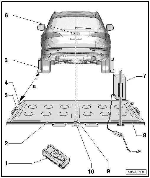
1 - Calibration Tool - Spacing Laser -VAS6350/2-
- For distance measurement
- For information on usage. Refer to the Operating Instructions.
2 - Calibration Tool -VAS6350-
3 - Level
- On the Calibration Tool -VAS6350-
- To check the horizontal position of the Calibration Tool -VAS6350-
4 - Catch Bracket
- To mount the Calibration Tool - Spacing Laser -VAS6350/2- for the distance measurement
- Distance to the Calibration Tool - Wheel Center Mountings -VAS6350/1- on the rear wheels: dimension -a- = 1700 +- 2 mm
5 - Calibration Tool - Wheel Center Mountings -VAS6350/1-
- With wheel bolt adapter and measuring paddle
6 - Brand Emblem
- The laser point is aligned on the center of the brand emblem
7 - Calibration Tool - Lane Change Calibration Tool -VAS6350/4-
- Is moved from one side of measuring field to the other during calibration
- When installed correctly, vehicle electrical system voltage line must be connected at bottom left of calibration device (as seen in direction of travel)
8 - Measurement Scale
- For positioning the Calibration Tool - Lane Change Calibration Tool -VAS6350/4-
9 - Calibration Tool - Linear Laser -VAS6350/3-
- With "laser eye protection"
- On the Calibration Tool -VAS6350-
- To turn on and off. Refer to the Calibration Tool -VAS6350- Operating Instructions.
10 - Plastic Foot
- Quantity: 3
- Can be adjusted for adjusting the horizontal position of the Calibration Tool -VAS6350-
Procedure
- Move the vehicle onto a solid, flat surface.
- Set the parking brake - the vehicle must not move during the measuring.
- Place the front wheels in a straight-ahead position - steering wheel in 0 position.
- Connect the vehicle diagnostic tester. Refer to Vehicle Diagnostic Tester.
 Note
Note
If a malfunction message appears in the display. Refer to Vehicle Diagnostic Tester.
- Turn on the ignition.
- Remove sticker with metal foil from bumper cover if necessary.
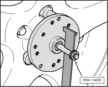
- Secure three suitable wheel bolt adapters for the wheel bolts on each Calibration Tool - Wheel Center Mountings -VAS6350/1-.
- Insert the measuring paddle on both Calibration Tool - Wheel Center Mountings -VAS6350/1- and secure with lock nut.
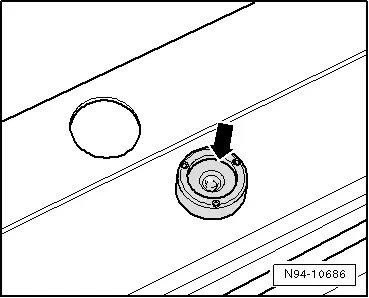
- Place the Calibration Tool - Wheel Center Mountings -VAS6350/1- onto the wheel bolts on both rear wheels.
- The wheel center sensor rotation center must be in wheel rotation center.
 Note
Note
Place the Calibration Tool - Wheel Center Mountings -VAS6350/1- on wheels so that "anti-theft wheel bolts" are not connected with wheel center mounting.
- Adjust the measuring paddle with aid of locking nuts so that they move freely just above the floor.
- The measuring paddles must move easily.
- The measuring paddles must be vertical.
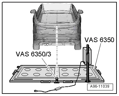
- Position the Calibration Tool -VAS6350- at distance -a- from rear wheels.
- Dimension -a- = 1700 mm.
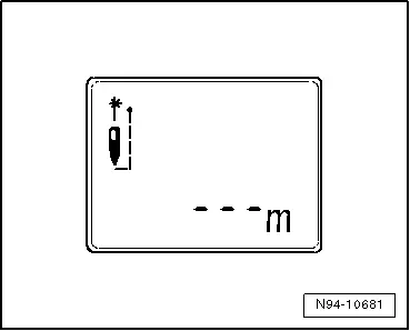
- Switch on the Calibration Tool - Spacing Laser -VAS6350/2- with the ON button.
Display on the Calibration Tool - Spacing Laser -VAS6350/2-:
- "- - - m"
 Note
Note
The laser is switched on at same time.
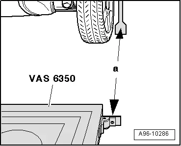
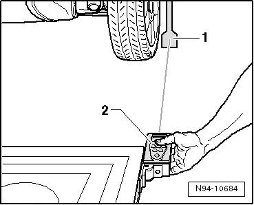
- For distance measurement, hold the Calibration Tool - Spacing Laser -VAS6350/2--2- flush to the right stop bracket as illustrated.
- The Calibration Tool - Spacing Laser -VAS6350/2- must lie firmly against the catch bracket.
- Make sure the "laser beam" for the distance measurement contacts the paddle on the lower enlarged part -1-.
If this is not the case, measure paddle height must be corrected using locking nuts on Calibration Tool - Wheel Center Mountings -VAS6350/1-.
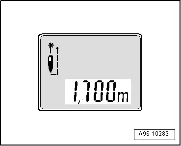
- Briefly press the ON button for distance measurement.
Display on the Calibration Tool - Spacing Laser -VAS6350/2-:
- "1.700 m" (specified value: 1700 +- 2 mm).
- Repeat measurement procedure from left catch bracket to left rear wheel.
- The distance value must be the same on both sides.
If both measured values are not the same, adjust the Calibration Tool -VAS6350- accordingly.
Performing Calibration
Vehicle Diagnostic Tester is attached.
- Choose operation mode Diagnosis and start the diagnosis.
- Select the tab test plan.
- Select select individual tests and choose the following sequence.
- Body
- Electrical Equipment
- 01 - OBD-capable systems
- 3C - Lane change assistance control module - J769
- 3C - Lane change assistance control module, functions
- 3C - Calibration
The Vehicle Diagnostic Tester continues with the calibrating procedure from here on.
 Note
Note
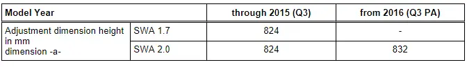
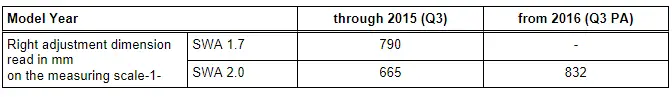
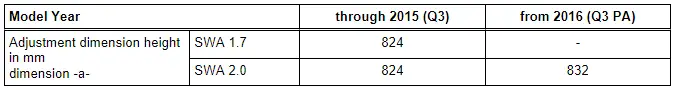
- The following information clarifies which version of the lane change assistance is installed (version SWA1.7).
- This information for adjusting the calibration device is important for later steps in the procedure to avoid malfunctions.
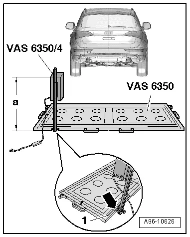
- Secure the Calibration Tool - Lane Change Calibration Tool -VAS6350/4- at right rear of the Calibration Tool -VAS6350- mount.
- When installed correctly, vehicle electrical system voltage line must be connected at bottom left of calibration device (as seen in direction of travel).
Dimension -a- is measured from the upper edge of calibration device to the floor.
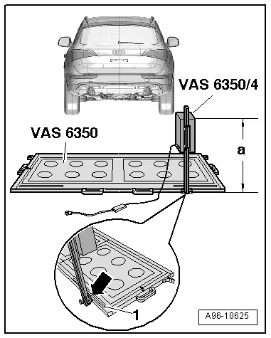
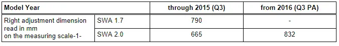
- The indicator on the base of the Calibration Tool - Lane Change Calibration Tool -VAS6350/4- must align with adjustment dimension on the measuring scale -1- on measuring field -arrow-.
- Connect the Calibration Tool - Lane Change Calibration Tool -VAS6350/4- to the vehicle electrical system voltage.
- Bring Calibration Device -VAS6350- into horizontal position by turning plastic base.
- Observe the bubble level (sight glass) on the Calibration Tool -VAS6350--arrow-.
- Switch on the Calibration Tool - Linear Laser -VAS6350/3- on the Calibration Tool -VAS6350-.
- Put on "Laser eye protection".
- Align the Calibration Tool -VAS6350- so that the Calibration Tool - Linear Laser -VAS6350/3- strikes the center of the brand emblem on the rear lid.
- Check the left and right distance between the catch bracket on the Calibration Tool -VAS6350- and measuring paddle -1- on wheel mountings again.
- Specified value: 1700 +- 2 mm
Calibration Procedure
The following should not occur during the calibration procedure:
- No metal reflectors may be located within a two m radius of the calibration device (for example, tool carts, metal cabinets).
- Vehicle doors must not be opened or closed.
- People should not sit in the vehicle.
- People must not go between the vehicle and the Calibration Tool - Lane Change Calibration Tool -VAS6350/4-.

Procedure
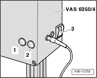
- Switch on the Calibration Tool - Lane Change Calibration Tool -VAS6350/4- at the power switch -3-.
- The green LED -1- must light up.
 Note
Note
If the red LED -2- illuminates: Check the Calibration Tool - Lane Change Calibration Tool -VAS6350/4-.
- Follow the instructions on the Vehicle Diagnostic Tester display.

During the course of the program, a request is made to switch the calibration unit for lane change assist -VAS6350/4- from the right to the left side of the Calibration Tool -VAS6350-.
- Switch the Calibration Tool - Lane Change Calibration Tool -VAS6350/4- off and move device.
- When installed correctly, vehicle electrical system voltage line must be connected at bottom left of calibration device (as seen in direction of travel).
Dimension -a- is measured from the upper edge of calibration device to the floor.
- The indicator on the base of the Calibration Tool - Lane Change Calibration Tool -VAS6350/4- must align with adjustment dimension on the measuring scale -1- on measuring field -arrow-.
- Switch on the Calibration Tool - Lane Change Calibration Tool -VAS6350/4- at the power switch -3-.
- The green LED -1- must light up.
- Follow the instructions on the Vehicle Diagnostic Tester display.
- After calibrating the lane change assistance successfully, end "calibration", switch off the ignition and disconnect the diagnostic connector.
READ NEXT:
 Driver Assistance Systems Front Camera
Driver Assistance Systems Front Camera Component Location Overview
1 - Retaining Plate
There are different versions. Refer to the Parts Catalog.
With heated windshield
Cannot be s
Trailer Hitch
Overview - Trailer Hitch Socket and Towing Recognition Control Module
1 - LED Indicator Lamp
Trailer Hitch -Locked- Indicator Lamp -K226-, Trailer Hitch
-Unlocked- Indicator Lamp -KSEE MORE:
Setting the central locking system
You can adjust the central locking system to your
preferences. The settings depend on the vehicle
equipment.
Applies to MMI: Select on the home screen: VEHICLE
> Settings & Service > Central locking.
Door unlocking
If you select All, all doors and the luggage compartment
lid will be
Parking aid plus
Activating and deactivating
Applies to: vehicles with parking aid plus
Fig. 111 Center console: parking aid button
General information
The parking aid assists when parking and maneuvering
by providing warnings about obstacles. If
the ultrasonic sensors on the vehicle fig. 88 detect an obstacle, th