Audi Q3: Overview - Antenna Systems
Audi Q3 (8U) 2011-2018 Service Manual / Electrical System / Communication / Antenna Systems / Overview - Antenna Systems
The antenna system consists of the Roof Antenna -R216- and the window antenna.
Roof Antenna -R216-
- GPS Antenna -R50-, only on 7T2, 7T6 and 7Q4
- Telephone Antenna -R65-, only on 9ZF and 9ZW
- Satellite Antenna -R170-, only North America and QV8
- Auxiliary Heater Antenna -R182-, only Europe and 9M9
Rear Window Antennas
- Digital Radio Antenna -R183- (DAB) to the Antenna Amplifier 4 -R113- on the right top of the rear lid near the Radio MOST
- Antenna -R11- (FM2) Antenna Amplifier 3 -R112- on the bottom left of the rear lid.
- Radio Antenna 2 -R93- (AM/FM1)/TV Antenna 1 -R55- (TV1) Antenna Amplifier -R24- on upper left of rear lid.
- TV Antenna 2 -R56- (TV2)/TV Antenna 3 -R57- (TV3) Antenna Amplifier 2 -R111- at the bottom of the right of the rear lid.
The Antenna Amplifier 4 -R113- with the DAB connection is only applicable to Europe and QV3.
Windshield Antenna
- Traffic Data Antenna -R173- ETC/VICS only Japan, 7T6
In the Instrument Panel
- Internet Antenna -R266-, W-LAN, UE2
Repairing the antenna wires. Refer to → Electrical Equipment General Information; Rep. Gr.97; Antenna Wires, Repairing.
Component Location Overview - Antenna Systems
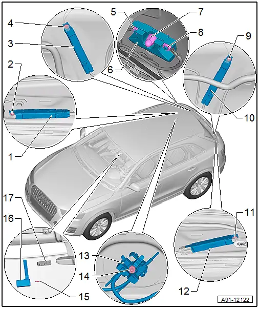
1 - Antenna Amplifier 4 -R113-
- Connector assignment.
- Removing and installing. Refer to → Chapter "Antenna Amplifier 4 -R113-, Removing and Installing".
2 - Bolt
- 2 Nm
3 - Antenna Amplifier 2 -R111-
- Connector assignment.
- Removing and installing. Refer to → Chapter "Antenna Amplifier 2 -R111-, Removing and Installing".
4 - Bolt
- 2 Nm
5 - Nut
- 9 Nm
6 - Windshield Antenna Suppression Filter -C18-
- Removing and installing. Refer to → Chapter "Windshield Antenna Suppression Filter -C18-, Removing and Installing".
7 - Nut
- 9 Nm
8 - Nut
- 9 Nm
9 - Bolt
- 2 Nm
10 - Antenna Amplifier 3 -R112-
- Connector assignment.
- Removing and installing. Refer to → Chapter "Antenna Amplifier 3 -R112-, Removing and Installing".
11 - Bolt
- 2 Nm
12 - Antenna Amplifier -R24-
- Connector assignment.
- Removing and installing. Refer to → Chapter "Antenna Amplifier -R24-, Removing and Installing".
13 - Roof Antenna -R216-
- Removing and installing. Refer to → Chapter "Roof Antenna, Removing and Installing".
14 - Nut
- 6 Nm
15 - Safety piece
16 - Traffic Data Antenna -R173-
- Removing and installing. Refer to → Chapter "Windshield Antenna Suppression Filter -C18-, Removing and Installing".
17 - Bracket
- Glued to the windshield
READ NEXT:
 Antenna Amplifier, Removing and Installing
Antenna Amplifier -R24-, Removing and Installing
The Antenna Amplifier -R24- is located on the upper left of
the rear lid.
Removing
- Turn off the ignition and all electrical equipment and
Roof Antenna, Removing and Installing
The Roof Antenna -R216- has up to three connectors.
The antenna wires are connected directly to the base of the
Roof Antenna -R216-.
The headliner must be lowered in order to remove the Roof
Ant
Antenna Amplifier Connector Assignments
Antenna Amplifier 4 -R113-
1 - Window antenna connection, Digital Radio Antenna -R183-
2 - DAB connection to the Radio -R-
3 - Not Assigned
Window Antenna Connector
SEE MORE:
Relay and Fuse Carriers Behind Instrument Panel on Driver Side, Removing and
Installing
Relay Carrier on Vehicle Electrical System Control Module, Removing and
Installing
Removing
- Remove the driver side instrument panel cover. Refer to
→ Body Interior; Rep. Gr.68; Storage Compartments/Covers; Driver
Side Instrument Panel Cover, Removing and Installing.
-
Sensors
Overview - Front Axle Speed Sensor
1 - Wheel Speed Sensor
Right Front ABS Wheel Speed Sensor -G45-/Left Front ABS Wheel Speed
Sensor -G47-
Removing and installing, refer to
→ Chapter "Right/Left Front ABS Wheel Speed Sensor -G45-/-G47-, Removing
and Installing".
2&
© 2019-2025 Copyright www.auq3.net
