Audi Q3: Sensors
Overview - Front Axle Speed Sensor
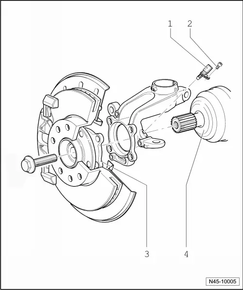
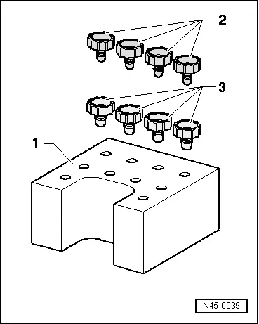
1 - Wheel Speed Sensor
- Right Front ABS Wheel Speed Sensor -G45-/Left Front ABS Wheel Speed Sensor -G47-
- Removing and installing, refer to → Chapter "Right/Left Front ABS Wheel Speed Sensor -G45-/-G47-, Removing and Installing".
2 - Bolt
- 8 Nm
3 - Wheel Hub with Wheel Bearing
- The ABS sensor ring is installed in the wheel bearing
4 - Drive Axle
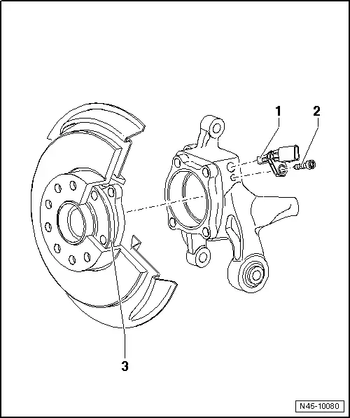
Overview - Rear Axle Speed Sensor
Front Wheel Drive
1 - Wheel Speed Sensor
- Right Rear ABS Wheel Speed Sensor -G44-/Left Rear ABS Wheel Speed Sensor -G46-
- Removing and installing, refer to → Chapter "Right/Left Rear ABS Wheel Speed Sensor -G44-/-G46-, Removing and Installing".
2 - Bolt
- 8 Nm
3 - Wheel Hub with Wheel Bearing
- The ABS sensor ring is installed in the wheel bearing
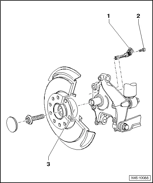
All Wheel Drive
1 - Wheel Speed Sensor
- Right Rear ABS Wheel Speed Sensor -G44-/Left Rear ABS Wheel Speed Sensor -G46-
- Removing and installing, refer to → Chapter "Right/Left Rear ABS Wheel Speed Sensor -G44-/-G46-, Removing and Installing".
2 - Bolt
- 8 Nm
3 - Wheel Bearing
- The ABS sensor ring is installed in the wheel bearing
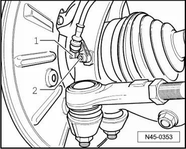
Right/Left Front ABS Wheel Speed Sensor -G45-/-G47-, Removing and Installing
Removing
- Disconnect the connector -1- from the speed sensor wire and the speed sensor.
- Remove the bolt -2- and remove the speed sensor from the wheel bearing housing.
Installing
Install in reverse order of removal. Note the following:
- Before inserting speed sensor, clean the inner surface of the hole and coat the speed sensor all around with hot bolt paste. For the correct hot bolt paste, refer to the Parts Catalog.
Right/Left Rear ABS Wheel Speed Sensor -G44-/-G46-, Removing and Installing
Removing
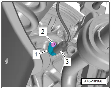
Vehicles with FWD:
- Disconnect the connector -3- from the speed sensor wire and the speed sensor -1-.
- Remove the bolt -2- and remove the speed sensor from the wheel bearing housing.
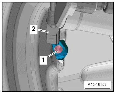
AWD Vehicles:
- Disconnect the connector -1- from the speed sensor wire and the speed sensor.
- Remove the bolt -2- and remove the speed sensor from the wheel bearing housing.
Installing
Install in reverse order of removal. Note the following:
- Before inserting speed sensor, clean the inner surface of the hole and coat the speed sensor all around with hot bolt paste. For the correct hot bolt paste, refer to the Parts Catalog.
Special Tools
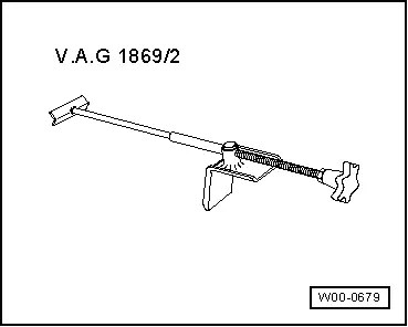
Special tools and workshop equipment required
- Brake Pedal Actuator -VAG1869/2-.
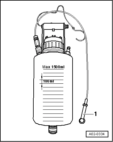
- Container -1- from the Brake Charger/Bleeder Unit -VAS5234-
- Plugs from Repair Kit -1H0 698 311 A-
READ NEXT:
 Overview - Front Brakes
Overview - Front Brakes, 1LJ 1ZD Brakes
1 - Bolt
12 Nm
2 - Brake Rotor
Allocation, refer to the Parts Catalog.
Dimensions, refer to
→ Chapter "Brakes
Front Brake Caliper Balance Weight
Depending on the model for each brake caliper two vibration
dampers are installed.
1 - Bolt
10 Nm
Replace after each removal.
2 - Vibration Damper
Installed 2 on
SEE MORE:
Rear cross-traffic assist
Description
Applies to: vehicles with rear cross-traffic assist
Fig. 118 Sensor detection range for rear cross-traffic assist
Fig. 119 Center display: rear cross-traffic assist display
General information
The rear cross-traffic assist monitors the area behind
and next to the vehicle using radar se
Visual Inspection
WARNING
Risk of injury. Follow all warning messages and
safety precautions. Refer to
→ Chapter "Warnings and Safety Precautions".
Before any extensive measurements are taken, visually
inspect the exterior of the battery, the connections, and the
secure installation of the
