Audi Q3: Overview - Front Brakes
Overview - Front Brakes, 1LJ 1ZD Brakes
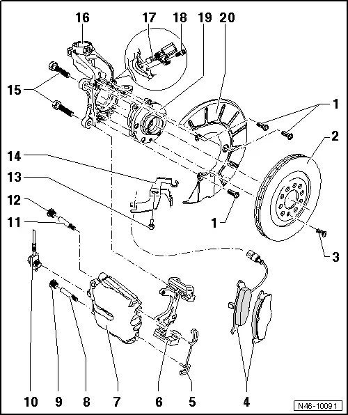
1 - Bolt
- 12 Nm
2 - Brake Rotor
- Allocation, refer to the Parts Catalog.
- Dimensions, refer to → Chapter "Brakes Technical Data"
- Wear limit.
- Must always be replaced together on both sides of the axle
- Do not use excessive force to separate the brake rotor from the wheel hub. If necessary, use rust penetrant, otherwise the brake rotors could be damaged.
- Removing and installing, refer to → Chapter "Brake Rotor, Removing and Installing, 1LJ, 1ZD Brakes".
3 - Bolt
- 4 Nm
4 - Brake Pads
- There are different versions, refer to the Parts Catalog.
- Check the brake pad thickness.
- Wear limit.
- Must always be replaced together on both sides of the axle
- Removing and installing, refer to → Chapter "Brake Pads, Removing and Installing, 1LJ, 1ZD Brakes".
- Observe the installation position, refer to → Fig.
5 - Spring
- Insert in both holes of brake caliper
6 - Brake Carrier
- Supplied as an assembled replacement part with sufficient grease on guide pins
- If the protective caps are damaged, install repair kit; use included grease packet to grease the guide pins.
7 - Brake Caliper
- Do not remove the brake hose when changing the brake pads.
- To replace brake pads, unfasten from brake carrier
- Removing and installing, refer to → Chapter "Brake Caliper, Removing and Installing, 1LJ, 1ZD Brakes".
- Replacing, refer to → Chapter "Brake Caliper, Replacing,1LJ, 1 ZD Brakes".
- Servicing, refer to → Chapter "Overview - Front Brake Caliper, Single-Piston Brake".
 Note
Note
- Depending on the model for each brake caliper two vibration dampers are installed.
8 - Guide Pin
- 30 Nm
9 - Cap
10 - Brake Hose
- To the brake caliper: 35 Nm
- To the brake line: 14 Nm
- With ring connection and banjo bolt
11 - Guide Pin
- 30 Nm
12 - Cap
13 - Bolt
14 - Bracket
15 - Ribbed Bolt
- 200 Nm
- Replace after removing
- Clean if using again.
16 - Wheel Bearing Housing
17 - Wheel Speed Sensor
- Removing and installing, refer to → Chapter "Overview - Front Axle Speed Sensor".
18 - Bolt
- 8 Nm
19 - Wheel Bearing Unit with Integrated Rotor
- Removing and installing, refer to → Suspension, Wheels, Steering; Rep. Gr.40; Wheel Bearing; Wheel Bearing Unit, Removing and Installing.
20 - Brake Shield
- Removing and installing, refer to → Chapter "Brake Shield, Removing and Installing, 1LJ, 1ZD Brakes".
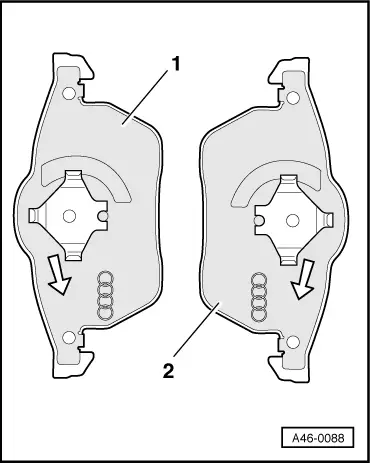
Installation Position of the Brake Pads
1 - Right brake pad, piston side
2 - Left brake pad, piston side
- In installed position, the arrow on the backing plate of the brake pad must point downward
Overview - Front Brakes, 1LA, 1ZT Brakes
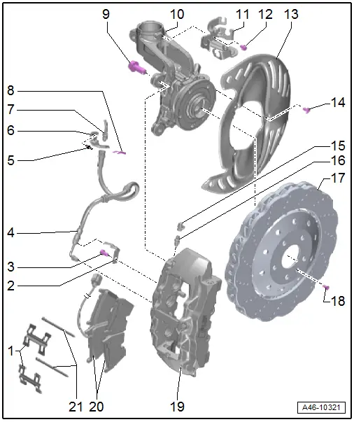
1 - Brake Pad Springs
- Replace when pads are replaced.
- Make sure then fits correctly inside the brake caliper
2 - Bracket
- For brake hose
3 - Bolt
- 8 Nm
4 - Brake Hose
- Tightening specification: brake hose to brake caliper, 15 Nm
- Make sure the brake hose is routed correctly. Make sure the brake hose is not blocked, bent or rubbing against the vehicle.
- Replace if damaged
- Make sure that lugs are properly seated in grooves in bracket.
5 - Rivet
6 - Bracket
- For brake hose
7 - Brake Line
- Tightening specification, brake line to brake hose, 14 Nm
8 - Spring
- Replace if damaged
9 - Bolt
- 200 Nm
- Replace after removing
- With a washer
- Quantity: 2
10 - Stub Axle Carrier
11 - Bracket
- For brake hose and electrical wire
12 - Bolt
- 8 Nm
13 - Cover Plate
- Removing and installing
14 - Bolt
- 12 Nm
15 - Protective Cap
16 - Bleed Screw
- 13 Nm
17 - Brake Rotor
- Wear limit.
- Allocation, refer to the Parts Catalog.
- Must always be replaced together on both sides of the axle
- Removing and installing, refer to → Chapter "Brake Rotor, Removing and Installing, 1LA, 1ZT Brakes".
18 - Bolt
- 4 Nm
19 - Brake Caliper
- May not be removed from the brake carrier, refer to → Fig. "Do Not Loosen the Brake Caliper/Brake Carrier and Tension Strut Threaded Connection"
- Allocation, refer to the Parts Catalog.
- Removing and installing, refer to → Chapter "Brake Caliper, Removing and Installing, 1LA, 1ZT Brakes".
- Replacing, refer to → Chapter "Brake Caliper, Replacing, 1LA, 1ZT Brakes".
- Servicing, refer to → Chapter "Overview - Front Brake Caliper, Eight-Piston Brake".
 Note
Note
- Depending on the model for each brake caliper two vibration dampers are installed.
- Refer to → Chapter "Brake Caliper Balance Weight"
20 - Brake Pads
- Check the brake pad thickness.
- Must always be replaced together on both sides of the axle
- Allocation, refer to the Parts Catalog.
- Removing and installing, refer to → Chapter "Brake Pads, Removing and Installing, Brakes 1LA, 1ZT".
- Note installed position: inner brake pad with brake pad wear sensor mount
21 - Brake Pad Pins
- Replace when pads are replaced.
- Note the installation position
- Drive out from the outside toward the inside
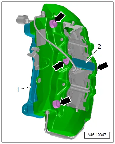
Do Not Loosen the Brake Caliper/Brake Carrier and Tension Strut Threaded Connection
 Caution
There is a risk of malfunctions.
The bolts -arrows- on the brake caliper for the brake carrier -1- and the tension strut -2- may not be loosened.