Audi Q3: Overview - Navigation System
Overview - Navigation System, General Information
- The navigation system is available on vehicles with Ready4Nav (7Q4), Navigation packet (7T2) and MMI navigation plus (7T6).
- The navigation system is part of the Information Electronics Control Module 1 -J794- inside the instrument panel.
- The operation takes place through the device itself.
- On the Ready4Nav (7Q4), all components for the navigation are installed (Radio concert MOST with GPS Antenna -R50-). The SD memory card does not contain the navigation data.
- For the navigation packet (7T2), the navigation data is stored on an SD card.
- For the MMI navigation plus (7TG), the navigation data is stored on an internal hard drive disc (HDD).
- MMI Navigation Plus - Japan: The Chip Card Reader Control Module -J676-is located in the glove compartment and the Traffic Data Antenna -R173- is located on the windshield.
Perform the Fault Finding with the Vehicle Diagnostic Tester.
Repairing the antenna wires. Refer to → Electrical Equipment General Information; Rep. Gr.97; Antenna Wires, Repairing.
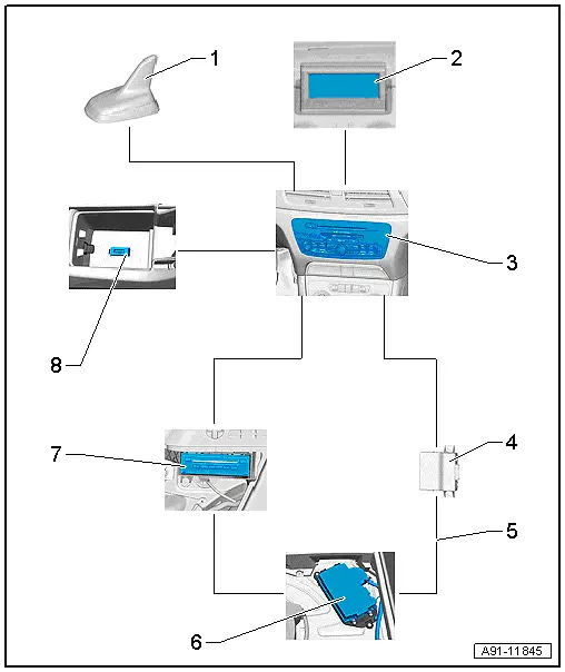
Overview - Navigation System, Ready4Nav 7Q4, Navigation Packet 7T2

1 - Roof Antenna -R216-
2 - Front Information Display Control Head -J685-
- In center of the instrument panel
3 - Information Electronics Control Module 1 -J794-
- Inside the instrument panel
4 - Data Bus On Board Diagnostic Interface -J533-
- Behind the driver side left compartment
5 - MOST Bus
6 - Digital Sound System Control Module -J525-
- In the right rear of the luggage compartment under the luggage compartment.
7 - CD Changer -R41-
- In the luggage compartment at the left behind the door
8 - External Audio Source Connection -R199-
- In the center console storage compartment
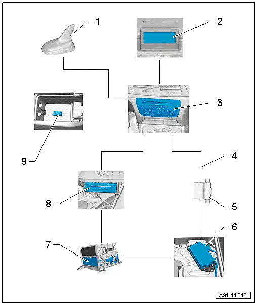
Overview - Navigation System, MMI Navigation Plus, 7T6

1 - Roof Antenna -R216-
2 - Front Information Display Control Head -J685-
- In center of the instrument panel
3 - Information Electronics Control Module 1 -J794-
- Inside the instrument panel
4 - MOST Bus
5 - Data Bus On Board Diagnostic Interface -J533-
- Behind the driver side left compartment
6 - Digital Sound System Control Module -J525-
- In the right rear of the luggage compartment under the luggage compartment.
7 - Radio -R-
- In the luggage compartment at the left behind the door
8 - CD Changer -R41-
- In the luggage compartment at the left behind the door
9 - External Audio Source Connection -R199-
- In the Center Console Storage Compartment
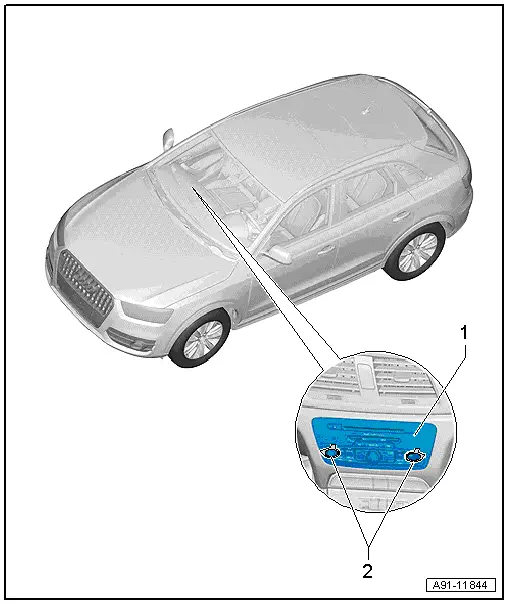
Component Location Overview - Navigation System
Component Location Overview - Navigation System, MMI Navigation Plus, 7T6

1 - Information Electronics Control Module 1 -J794-
- Ready4Nav connector assignment. Refer to → Chapter "Connector Assignments, Ready4Nav 7Q4, Navigation Packet 7T2".
- MMI navigation plus connector assignment. Refer to → Chapter "Connector Assignment, MMI Navigation Plus, 7T6".
- Removing and installing. Refer to → Chapter "Information Electronics Control Module 1 -J794-, Removing and Installing".
2 - Radio Removal Tool -T10057-

