Audi Q3: Anti-Theft Alarm System
Overview - Interior Monitoring
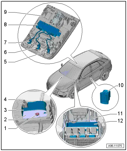
1 - Nut
- 7 Nm
2 - Bracket
- For Alarm Horn -H12-
3 - Alarm Horn -H12-
- Removing and installing. Refer to → Chapter "Alarm Horn -H12-, Removing and Installing".
4 - Connector
5 - Right Interior Monitoring Individual Sensor
- Can only be replaced together with the Anti-Theft Alarm System Sensor -G578-
6 - Individual Sensor
- For Anti-Theft Alarm System Sensor -G578-
- Removing and installing. Refer to → Chapter "Anti-Theft Alarm System Sensor -G578-, Removing and Installing".
7 - Left Interior Monitoring Individual Sensor
- Can only be replaced together with the Anti-Theft Alarm System Sensor -G578-
8 - Anti-Theft Alarm System Sensor -G578-
- Removing and installing. Refer to → Chapter "Anti-Theft Alarm System Sensor -G578-, Removing and Installing".
9 - Front Interior Lamp/Reading Lamp
10 - Interior Monitoring Switch -E183-
- Removing and installing. Refer to → Chapter "Passenger Compartment Monitoring Switch -E183-, Removing and Installing".
11 - Relay/Fuse Panel
12 - Vehicle Electrical System Control Module -J519-
- With Central Locking and Anti-Theft Alarm System Antenna -R47-
- Overview. Refer to → Chapter "Overview - Instrument Panel Relay Carrier/Fuse Carrier and A-Pillar Relay Carrier/Fuse Carrier".
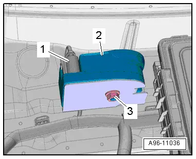
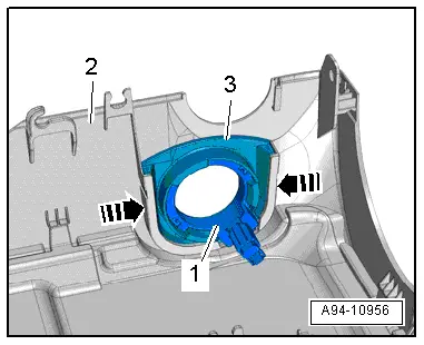
Alarm Horn -H12-, Removing and Installing
Removing
- Remove the plenum chamber cover. Refer to → Body Exterior; Rep. Gr.50; Bulkhead; Plenum Chamber Cover, Removing and Installing.
- Disconnect the connector -1-.
- Remove the nut -3-.
- Remove the alarm horn -2- to the right.
Installing
Install in reverse order of removal. Note the following:
- Install the plenum chamber cover. Refer to → Body Exterior; Rep. Gr.50; Bulkhead; Plenum Chamber Cover, Removing and Installing.
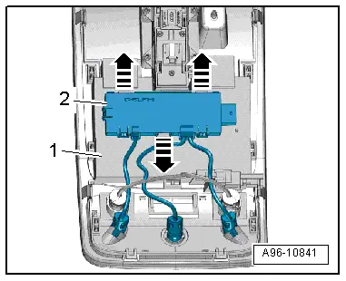
Anti-Theft Alarm System Sensor -G578-, Removing and Installing
Removing
- Remove the front interior/reading lamp. Refer to → Chapter "Front Interior Lamp/Reading Lamp, Removing and Installing".
- Release the retaining tabs in direction of -arrows- and remove the Anti-Theft Alarm System Sensor -G578--2- from the interior lamp/reading lamp -1-.
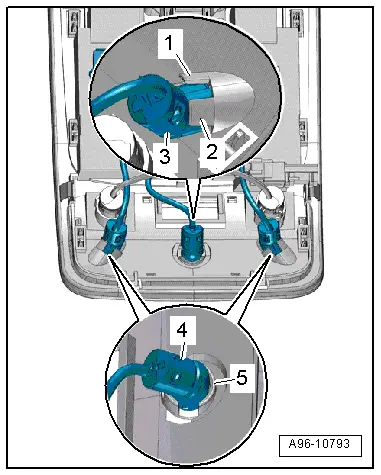
- Release the tabs -1 and 2- and remove the center individual sensor -3- from the interior lamp/reading lamp.
- Release the tab -5- and remove the left and right individual sensors -4- from the interior lamp/reading lamp.
Installing
Install in reverse order of removal. Note the following:
- Install the front interior lamp/reading lamp. Refer to → Chapter "Front Interior Lamp/Reading Lamp, Removing and Installing".
Immobilizer
Anti-Theft Immobilizer Reader Coil, Removing and Installing
Removing
- Adjust steering wheel downward and to rear as far as possible, use entire adjustment range of steering column adjustment for this.
- Remove the trim for the steering column switch module. Refer to → Body Interior; Rep. Gr.68; Storage Compartments/Covers; Overview - Steering Column Trim Panel.
- Release the tabs in direction of -arrows- and remove the mount -3- upward out of the lower steering column switch module trim -2-.
- Remove the reader coil -1- from the mount.
Installing
Install in reverse order of removal. Note the following:
- Press the reader coil into the mount until it engages audibly.
- Install the trim for the steering column switch module. Refer to → Body Interior; Rep. Gr.68; Storage Compartments/Covers; Overview - Steering Column Trim Panel.
READ NEXT:
 Lane Change Assistance
Overview - Lane Change Assistance
1 - Lane Change Assistance Button -E530-
Removing and installing. Refer to
→ Chapter "Lane Change Assistance Button -E530-, Removing and
I
Lane Change Assistance, Calibrating
Special tools and workshop equipment
required
Calibration Tool -VAS6350-
Conditions
- The Lane Change Assistance Control Module -J769-/ Lane
Change Assistance Control Module 2 -J770-
Driver Assistance Systems Front Camera
Driver Assistance Systems Front Camera Component Location Overview
1 - Retaining Plate
There are different versions. Refer to the Parts Catalog.
With heated windshield
Cannot be s
SEE MORE:
Front Bumper Cover, Removing and Installing
Bumper Cover, Removing and Installing
Removing
- Remove the front wheel spoiler. Refer to
→ Chapter "Front Wheel Spoiler, Removing and Installing".
- Remove the front wheel housing liner. Refer to
→ Chapter "Front Wheel Housing Liner, Removing and Installing".
- C
Component Location Overview - Luggage Compartment Trim Panels
1 - Lock Carrier Trim
Overview. Refer to
→ Chapter "Overview - Lock Carrier Trim".
2 - Luggage Compartment Floor Covering
Overview. Refer to
→ Chapter "Overview - Luggage Compartment Floor".
3 - Luggage Compartment Side Trim Panel
O
