Audi Q3: Deformation Element
Overview - Deformation Element
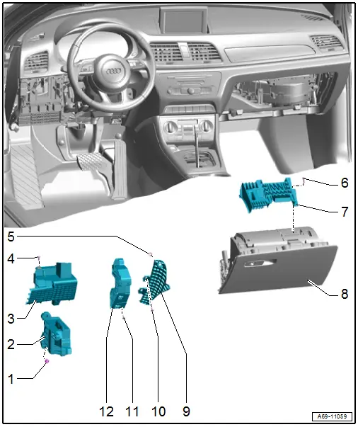
1 - Nut
- 25 Nm
- Quantity: 3
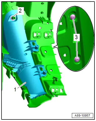
2 - Lower Deformation Element
- Component location: under the instrument panel on the driver side
- Removing and installing. Refer to → Chapter "Lower Deformation Element, Removing and Installing, Driver Side".
3 - Upper Outer Deformation Element
- Component location: under the instrument panel on the driver side
- Removing and installing. Refer to → Chapter "Upper Outer Deformation Element, Removing and Installing, Driver Side".
4 - Bolt
- 3 Nm
- Quantity: 2
5 - Lock Washer
- Replace after removing
- Press on until stop
6 - Bolt
- Quantity: 4
- 1.5 Nm
7 - Front Passenger Side Deformation Element
- Component location: on the glove compartment
- Removing and installing. Refer to → Chapter "Front Passenger Side Deformation Element, Removing and Installing".
8 - Glove Compartment
- Removing and installing. Refer to → Chapter "Glove Compartment, Removing and Installing".
9 - Instrument Panel Deformation Element
- Component location: on the left side of the instrument panel
- Removing and installing. Refer to → Chapter "Instrument Panel Deformation Element, Removing and Installing".
10 - Bolt
- 1.5 Nm
- Quantity: 2
11 - Bolt
- 1.5 Nm
- Quantity: 3
12 - Upper Inner Deformation Element
- Component location: under the instrument panel on the driver side
- Removing and installing. Refer to → Chapter "Upper Inner Deformation Element, Removing and Installing, Driver Side".
Deformation Element, Removing and Installing
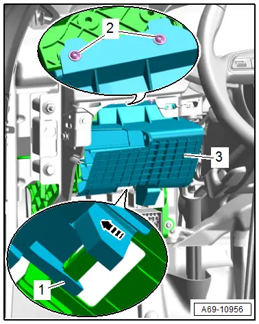
Upper Outer Deformation Element, Removing and Installing, Driver Side
Removing
- Remove the instrument panel cover on the driver side. Refer to → Chapter "Driver Side Instrument Panel Cover, Removing and Installing".
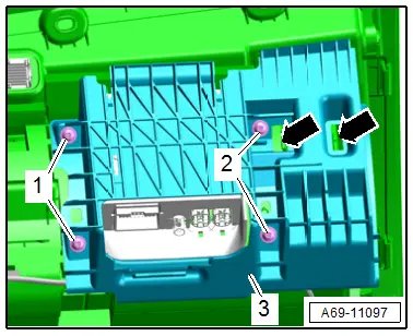
- Remove the bolts -2-.
- Release the hook -1- and remove the deformation element -3- from the relay and fuse carrier toward the rear -arrow-.
Installing
Install in reverse order of removal.
Installation notes, for example tightening specifications, replacing components. Refer to → Chapter "Overview - Deformation Element".
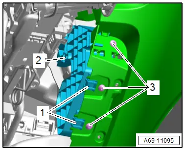
Upper Inner Deformation Element, Removing and Installing, Driver Side
Removing
- Remove the instrument panel cover on the driver side. Refer to → Chapter "Driver Side Instrument Panel Cover, Removing and Installing".
- Remove the lower steering column trim panel. Refer to → Chapter "Lower Steering Column Trim Panel, Removing and Installing".
- Move the steering wheel as far up and backward as possible to be able to use the full steering column adjustment range.
- Unclip the deformation element wire and free it up.
- Remove the bolts -3-.
- Release the hook -1- and remove the deformation element -2- from the instrument panel.
Installing
Install in reverse order of removal.
Installation notes, for example tightening specifications, replacing components. Refer to → Chapter "Overview - Deformation Element".
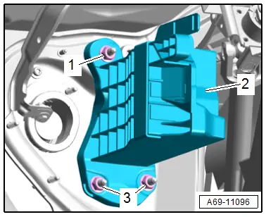
Lower Deformation Element, Removing and Installing, Driver Side
Removing
- Remove the instrument panel cover on the driver side. Refer to → Chapter "Driver Side Instrument Panel Cover, Removing and Installing".
- Remove the upper outer deformation element. Refer to → Chapter "Upper Outer Deformation Element, Removing and Installing, Driver Side".
- Remove the relay and fuse carrier behind the driver side instrument panel. Refer to → Electrical Equipment; Rep. Gr.97; Relay Panel, Fuse Panel and E-Boxes; Relay and Fuse Carrier behind Driver Side Instrument Panel, Removing and Installing.
- Remove the nuts -1 and 3-.
- Disengage the deformation element -2- at the pins and remove.
Installing
Install in reverse order of removal.
Installation notes, for example tightening specifications, replacing components. Refer to → Chapter "Overview - Deformation Element".
Instrument Panel Deformation Element, Removing and Installing
Removing
- Remove the instrument panel. Refer to → Chapter "Instrument Panel, Removing and Installing".
- Remove the bolts -3-.
- Remove the lock washer -2- and remove the deformation element -1- from the instrument panel.
Installing
Install in reverse order of removal.
Installation notes, for example tightening specifications, replacing components. Refer to → Chapter "Overview - Deformation Element".
Front Passenger Side Deformation Element, Removing and Installing
Removing
- Remove the glove compartment. Refer to → Chapter "Glove Compartment, Removing and Installing".
- Remove the bolts -1 and 2-.
- Unclip the deformation element -3- from the glove compartment -arrows- and remove.
Installing
Install in reverse order of removal.
Installation notes, for example tightening specifications, replacing components. Refer to → Chapter "Overview - Deformation Element".
Special Tools
Special tools and workshop equipment required
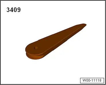
- Trim Removal Wedge -3409-
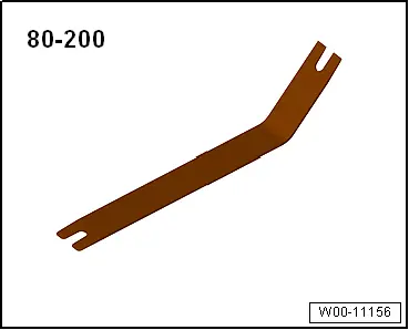
- Pry Lever -80-200-
- TORX screwdriver T25, approximately 100 mm long, commercially available
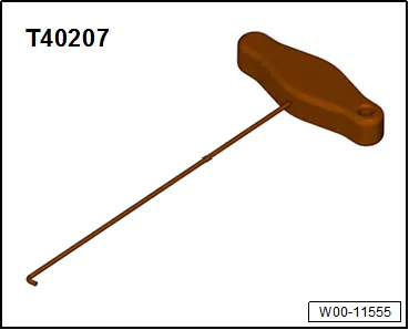
- Hook Tool -T40207-
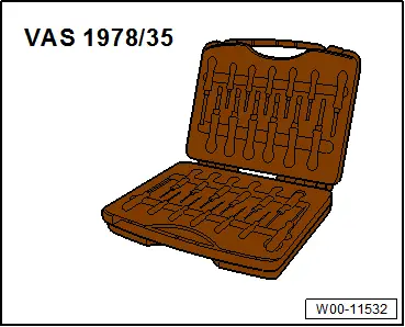
- Release Tool Set - Extraction Tool 17 -VAS1978/17- from the Release Tool Set -VAS1978/35-
READ NEXT:
 Overview - Front Door Trim Panel
1 - Pull Handle
With switch mount
Removing and installing. Refer to
→ Chapter "Front Pull Handle, Removing and Installing".
2 - Left Front Entry Lamp -W31-
Midrange Speaker Trim, Removing and Installing
Special tools and workshop equipment
required
Wedge Set -T10383-
Removing
- Pry out the speaker trim -1-
along the door trim seam -arrow-
using the Wedge -T10383/1- and remove it.
SEE MORE:
Refrigerant Cut-Off Valve
Note
There are different versions of the shut-off valve with
different functions and with different names. The following
illustrated Hybrid Battery Refrigerant Shut-Off Valve 1 -N516-
is for example installed on an Audi Q7 hybrid. Refer to
→ Heating, Ventilation and Air Co
Driver Side Footwell Vent, Removing and Installing
Removing
- Remove the driver side instrument panel cover. Refer to
→ Body Interior; Rep. Gr.68; Storage Compartments and Covers;
Driver Side Instrument Panel Cover, Removing and Installing.
- Remove the bolt -1-.
- Remove the footwell vent -2-.
Installing
Inst
