Audi Q3: DVD/CD Changer
CD Changer, Removing and Installing
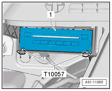
The CD Changer -R41- is behind the left luggage compartment trim panel.
 Note
Note
If replacing the control module, select the "Replace control module" function for the corresponding control module on the Vehicle Diagnostic Tester.
Special tools and workshop equipment required
- Radio Removal Tool -T10057-
- Fiber Optic Repair Set -VAS6223B-
- Fiber-Optic Repair Set - Connector Protective Caps -VAS6223/9-.
Removing
- Turn off the ignition and all electrical equipment and remove the ignition key.
- Remove the cover from the left side of the luggage compartment.
- Insert the two clips on the Radio Removal Tool -T10057- in the release slits on the CD Changer -R41--1- until they engage. Points on the grip eyelets of tool face outward.
- Remove the CD Changer -R41--1- from the frame.
- Disconnect all of the connectors from the CD Changer -R41-.
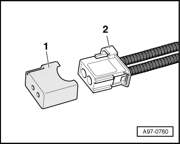
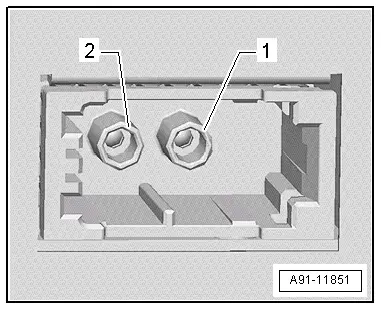
- Insert the Fiber-Optic Repair Set - Connector Protective Caps -VAS6223/9--1- onto the MOST bus connector -2-.
- Press the locking latches on the CD Changer -R41- to remove the Radio Removal Tool -T10057-.
Installing
- Install in reverse order of removal. Note the following:
- Connect all the connectors.
- Push the CD Changer -R41- into the mounting frame until it engages.
Connector Assignments
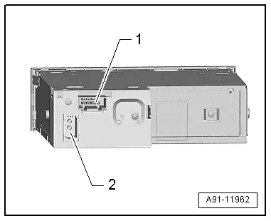
CD Changer -R41-
1 - 8-Pin Connector -T8aa-
2 - MOST Bus
 Note
Note
Unlisted connector terminals are not assigned.
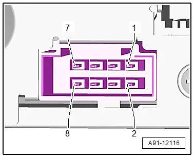
1 -8-Pin Connector -T8aa-
1 - Terminal 31
2 - Terminal 30
5 - Ring-break Diagnostic Cable
2 - MOST bus
1 - Output
2 - Input
READ NEXT:
 Overview - Telephone
Overview - Telephone, Cell Phone Pre-Installation, 9ZF
Cell Phone Preparation in Information Electronics Control
Module 1 -J794-, Concert MOST, 9ZF
The Telephone Baseplate -R126- is installed in t
Overview - Microphone Unit
The Microphone Unit In Front Roof Module -R164- is installed
in the Front Interior Lamp -W1-. Up to three microphones may be
installed, depending on the equipment.
One microphone (Interior Microp
SEE MORE:
Overview - Door
1 - Door
Removing and installing. Refer to
→ Chapter "Door, Removing and Installing".
2 - Bolt
45 Nm
Note
The bolt is a fitting bolt so it is generally not necessary to
adjust the door using it.
If it is necessary to make an adjustment us
Drive Axle, Removing and Installing
Removing
- Measure dimension from center of wheel to lower edge of
wheel housing. Refer to
→ Chapter "Wheel Bearing in Curb Weight, Lifting Vehicles with
Coil Spring".
- Loosen the drive axle threaded connection. Refer to
→ Chapter "Drive Axle Threaded Connection, Lo
