Audi Q3: Heating Output, Checking
Heating Output, Checking
 Note
Note
This repair manual only outlines the checking procedure. Perform the detailed function test for the heating as described in the Guided Fault Finding using the Vehicle Diagnostic Tester in the "Guided Fault Finding" function.
Special tools and workshop equipment required
- Vehicle Diagnostic Tester
- A standard thermometer (for temperature measurements, if necessary a thermometer with two measuring probes for simultaneous measurement, for example, for temperature on the right and left)
- If the coolant circuit is not completely bled after filling, air may accumulate in the heater core for the heater, reducing heating output. Additional noises may occur or the customer may report different air temperatures coming out of the driver and passenger side vents.
Corrective action for poor heating output or noises from coolant circuit:
- Perform a test drive at high engine speed (at least 10 minutes, engine speed above 2500 RPM), while selecting a low gear to prevent excessive vehicle speed.
- If the customer complains of poor heating output at certain engine speeds, check the incorporation of the heater core for the heater in the engine coolant circuit. Refer to → Engine Mechanical, Fuel Injection and Ignition; Rep. Gr.19; Cooling System/Coolant; Connection Diagram - Coolant Hoses.
 Note
Note
- For vehicles with the start-stop function and manual climate control system (heater without A/C system), the stop function is disabled depending on the setting on the A/C Control Module -J301- (the Heater Control Module -J65-) control head (for example, the heater is on). As soon as there is a request for heating, the engine is started. In the cooling mode, the A/C Control Module -J301- (the Heater Control Module -J65-) does not limit the stop function.
- For vehicles with a start-stop function and an automatic climate control system, the stop function is disabled depending on the setting on the Climatronic Control Module -J255- control head. If, for example, "Defrost" mode is selected, the stop function is not possible or is cancelled and the engine is started as soon as this mode is selected. The same applies in the case of heating and cooling mode. The difference between the selected target and measured actual temperature exceeds a certain value. Refer to Vehicle Diagnostic Tester.
- For vehicles with the Start/Stop System, there is currently no additional coolant pump installed for the start-stop function. Depending on the engine, however, an electrical coolant pump that is activated by the engine control module may be present. Refer to → Engine Mechanical, Fuel Injection and Ignition; Rep. Gr.19; Coolant Pump/Thermostat; Overview - Electric Coolant Pump and → Wiring diagrams, Troubleshooting & Component locations.
- Depending on the engine version to support the engine coolant pump an After-Run Coolant Pump -V51-/Heater Support Pump -V488- may be installed (different designations depending on the engine). Refer to → Engine Mechanical; Rep. Gr.19; Coolant System/Coolant (Connection Diagram for Coolant Hoses) and → Wiring diagrams, Troubleshooting & Component locations. The After-Run Coolant Pump -V51-/Heater Support Pump -V488- can be actuated in "stop mode" (engine stopped) to maintain the coolant flow rate through the heater core for the heater on with a cold engine or on vehicles with a Start/Stop System.
Heating Output, Checking, Heater without A/C System
Test Prerequisites
- The coolant circuit has been bled according to the specifications. Refer to → Engine Mechanical, Fuel Injection and Ignition; Rep. Gr.19; Cooling System/Coolant; Coolant, Draining and Filling
- All air guides, covers and seals are OK and properly installed.
- The airflow through the dust and pollen filter is not affected by dirt in the filter. To check, refer to → Chapter "Dust and Pollen Filter, Removing and Installing".
- The Temperature Regulator Door Motor -V68- and the related doors reach their end position. To check, refer to "Guided Fault Finding"Vehicle Diagnostic Tester.
- The vehicle is not exposed to sunlight.
- The engine is warm.
- The Diagnostic Trouble Code (DTC) memory for the Heater Control Module -J65- control head was checked and erased and the basic setting was performed in the "Guided Fault Finding" function on the Vehicle Diagnostic Tester.
Checking
 Note
Note
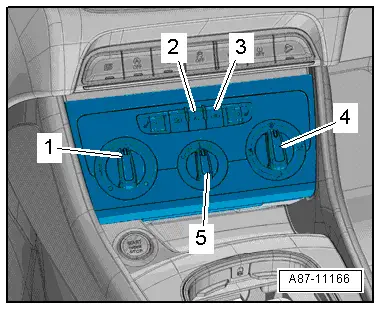
This illustration shows an A/C control head for a manual climate control system (the A/C Control Module -J301-). For the Heater Control Module -J65- (on a vehicle without an A/C system), A/C button -2- is not present.
- Close the engine hood, doors, windows and sunroof.
- Open all instrument panel vents.
- Start the engine and adjust the following settings on the control head:
- Turn the temperature knob -1- to the "cold" stop.
- Let the heater run several minutes with the "cold" setting (with the engine running).
- Measure the ambient temperature near the windshield.
- Turn the air distribution knob -4- to the "instrument panel vent" stop.
- Turn the knob -5- for the fresh air blower to level "4".
- Measure temperature of the air flowing out of left and right instrument panel vents using a thermometer.
Specified values:
- If the measured value for the Evaporator Vent Temperature Sensor -G263- is evaluated using the Vehicle Diagnostic Tester (in the "Guided Fault Finding" function). Compare the measured values with the displayed measured value (of the Evaporator Vent Temperature Sensor -G263-). The measured values may not be smaller and after 5 minutes, may be a maximum of 5 ºC (41 ºF) greater than the value of the Evaporator Vent Temperature Sensor -G263-.
- If the measured value for the Evaporator Vent Temperature Sensor -G263- is not evaluated using the Vehicle Diagnostic Tester (in the "Guided Fault Finding" function). After five minutes, the temperature of the air coming out the left and right instrument panel vents may be a maximum 15 ºC (59 ºF) greater than the ambient temperature measured beforehand.

- Set the highest possible temperature.
- Turn the temperature regulator -1- to the "warm" stop.
- Measure temperature of the air flowing out of left and right instrument panel vents using a thermometer.
Specified values:
- Temperature increases to greater than 55 ºC (131 ºF) (at an engine temperature of approximately 90 ºC (194 ºF) ). The deviation between the left and right side is less than 8 ºC (46 ºF) .
- Set the lowest temperature possible (temperature knob at "cold" stop).
- Measure temperature of the air flowing out of left and right instrument panel vents using a thermometer.
Specified values:
- If the measured value for the Evaporator Vent Temperature Sensor -G263- is evaluated using the Vehicle Diagnostic Tester (in the "Guided Fault Finding" function). Compare the measured values with the displayed measured value (of the Evaporator Vent Temperature Sensor -G263-). The measured values may not be smaller and after 5 minutes, may be a maximum of 5 ºC (41 ºF) greater than the value of the Evaporator Vent Temperature Sensor -G263-.
- If the measured value for the Evaporator Vent Temperature Sensor -G263- is not evaluated using the Vehicle Diagnostic Tester (in the "Guided Fault Finding" function). After five minutes, the temperature of the air coming out the left and right instrument panel vents may be a maximum 15 ºC (59 ºF) greater than the ambient temperature measured beforehand.
If the specified values are not reached, check the following:
- The coolant circuit bleeding. Refer to → Engine Mechanical, Fuel Injection and Ignition; Rep. Gr.19; Cooling System/Coolant; Coolant, Draining and Filling
- The incorporation of the heater core for the heater in the coolant circuit. Refer to → Engine Mechanical, Fuel Injection and Ignition; Rep. Gr.19; Cooling System/Coolant; Connection Diagram - Coolant Hoses
- Foam seal on the heater core for the heater. Refer to → Chapter "Heater Core, Removing and Installing".
- Check the activation and function of the Temperature Regulator Door Motor -V68- using the Vehicle Diagnostic Tester in the "Guided Fault Finding" function.
- Function of temperature door in air distribution housing. Refer to → Chapter "Overview - Air Distribution Housing Doors and Partitions".
- Check the coolant thermostat (if the thermostat is faulty, the engine coolant temperature may not be warm enough). Refer to → Rep. Gr.19; Coolant Pump/Thermostat.
- If equipped, the function of the After-Run Coolant Pump -V51-/Heater Support Pump -V488- (different designations depending on the engine). Refer to → Engine Mechanical; Rep. Gr.19; Coolant System/Coolant.
 Note
Note
Depending on the engine version to support the engine coolant pump an After-Run Coolant Pump -V51-/Heater Support Pump -V488- may be installed (different designations depending on the engine). Refer to → Engine Mechanical; Rep. Gr.19; Coolant System/Coolant (Connection Diagram for Coolant Hoses) and → Wiring diagrams, Troubleshooting & Component locations. The After-Run Coolant Pump -V51-/Heater Support Pump -V488- can be actuated in "stop mode" (engine stopped) to maintain the coolant flow rate through the heater core for the heater on with a cold engine or on vehicles with a Start/Stop System.
Heating Output, Checking, Manual Climate Control System
Test Prerequisites
- The coolant circuit has been bled according to the specifications. Refer to → Engine Mechanical, Fuel Injection and Ignition; Rep. Gr.19; Cooling System/Coolant; Coolant, Draining and Filling
- All air guides, covers and seals are OK and properly installed.
- The airflow through the dust and pollen filter is not affected by dirt in the filter. To check, refer to → Chapter "Dust and Pollen Filter, Removing and Installing".
- If the A/C cooling output is checked and found to be OK, refer to → Chapter "Cooling Output, Checking".
- The vehicle is not exposed to sunlight.
- The engine is warm.
- The Diagnostic Trouble Code (DTC) memory for the A/C Control Module -J301- control head was checked and erased and the basic setting was performed in the "Guided Fault Finding" function on the Vehicle Diagnostic Tester.
Checking
- Close the engine hood, doors, windows and sunroof.
- Open all instrument panel vents.
- Start the engine and adjust the following settings on the control head:
- Turn the temperature knob -1- to the "cold" stop.
- The A/C compressor is on - the indicator lamp in the AC or A/C button -2- illuminates.
- Let the A/C system run for several minutes at maximum cooling output (while the engine is running).
- Turn the air distribution knob -4- to the "instrument panel vent" stop.
- Turn the knob -5- for the fresh air blower to level "4".
- Measure temperature of the air flowing out of left and right instrument panel vents using a thermometer.
- Compare the measured values with the displayed measured value (for the Evaporator Vent Temperature Sensor -G263-). The measured values may not be smaller and after 5 minutes, may be a maximum of 3 ºC (37 ºF) greater than the value of the Evaporator Vent Temperature Sensor -G263-.
Specified values:
- Temperature maximum 12 ºC (54 ºF), depending on ambient temperature, the difference between the measured values is less than 3 ºC (37 ºF).

- Set the highest possible temperature.
- Turn the temperature regulator -1- to the "warm" stop.
- Measure temperature of the air flowing out of left and right instrument panel vents using a thermometer.
Specified values:
- Temperature increases to greater than 55 ºC (131 ºF) (at an engine temperature of approximately 90 ºC (194 ºF) ). The deviation between the left and right side is less than 8 ºC (46 ºF).
- Set the lowest temperature possible (temperature knob at "cold" stop).
- Measure temperature of the air flowing out of left and right instrument panel vents using a thermometer.
Specified values:
- Temperature decreases within 5 minutes to less than 12 ºC (54 ºF) depending on ambient temperature.
If the specified values are not reached, check the following:
- The coolant circuit bleeding. Refer to → Engine Mechanical, Fuel Injection and Ignition; Rep. Gr.19; Cooling System/Coolant; Coolant, Draining and Filling
- The incorporation of the heater core for the heater in the A/C unit into the coolant circuit. Refer to → Engine Mechanical, Fuel Injection and Ignition; Rep. Gr.19; Cooling System/Coolant; Connection Diagram - Coolant Hoses.
- The foam seal on heater core for heater of A/C unit → Chapter "Heater Core, Removing and Installing".
- Check the activation and function of the Temperature Regulator Door Motor -V68- using the Vehicle Diagnostic Tester in the "Guided Fault Finding" function.
- Function of temperature door in air distribution housing. Refer to → Chapter "Overview - Air Distribution Housing Doors and Partitions".
- Check the coolant thermostat (if the thermostat is faulty, the engine coolant temperature may not be warm enough). Refer to → Rep. Gr.19; Coolant Pump/Thermostat.
- If equipped, the function of the After-Run Coolant Pump -V51-/Heater Support Pump -V488- (different designations depending on the engine). Refer to → Engine Mechanical; Rep. Gr.19; Coolant System/Coolant.
 Note
Note
Depending on the engine version to support the engine coolant pump an After-Run Coolant Pump -V51-/Heater Support Pump -V488- may be installed (different designations depending on the engine). Refer to → Engine Mechanical; Rep. Gr.19; Coolant System/Coolant (Connection Diagram for Coolant Hoses) and → Wiring diagrams, Troubleshooting & Component locations. The After-Run Coolant Pump -V51-/Heater Support Pump -V488- can be actuated in "stop mode" (engine stopped) to maintain the coolant flow rate through the heater core for the heater on with a cold engine or on vehicles with a Start/Stop System.

Heating Output, Checking, Automatic Climate Control System
Test Prerequisites
- The coolant circuit has been bled according to the specifications. Refer to → Engine Mechanical, Fuel Injection and Ignition; Rep. Gr.19; Cooling System/Coolant; Coolant, Draining and Filling
- All air guides, covers and seals are OK and properly installed.
- The airflow through the dust and pollen filter is not affected by dirt in the filter. Refer to → Chapter "Dust and Pollen Filter, Removing and Installing".
- If the Air Conditioning (A/C) cooling output is checked and found to be OK, refer to → Chapter "Cooling Output, Checking".
- The vehicle is not exposed to sunlight.
- The engine is warm.
- The Diagnostic Trouble Code (DTC) memory for the Climatronic Control Module -J255- control head was checked and erased and the basic setting was performed on the Vehicle Diagnostic Tester in the "Guided Fault Finding" function.
- The coding and adaptation of the Climatronic Control Module -J255- control head in the "Guided Fault Finding" function on the Vehicle Diagnostic Tester.
Checking
- Close the engine hood, doors, windows and sunroof.
- Open all instrument panel vents.
- Start the engine and adjust the following settings on the control head:
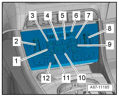
- Set the temperature preset "cold" via the temperature preset knobs -2 and 8- - "LO" for the driver and front passenger side in the display -6- on the Climatronic Control Module -J255-.
- The A/C compressor is on - the indicator lamp in the AC or A/C button -1- illuminates.
- Set the air distribution to the instrument panel vents -9-.
- Let the A/C system run for several minutes at maximum cooling output (while the engine is running).
- Read the measured values for the Left/Right Vent Temperature Sensor-G150-/-G151- in the "Guided Fault Finding" function on the Vehicle Diagnostic Tester.
- Compare the displayed measured values with each other.
Specified values:
- Temperature maximum 12 ºC (54 ºF) (depending on ambient temperature), deviation between measured values less than 3 ºC (37 ºF).
 Note
Note
Using a hand, check if there is actually air coming out of the activated vents.
- Set the highest possible temperature for the driver side.
- Set the temperature preset "warm" via the knob -2-: "HI" for the driver side in the display -6- on the Climatronic Control Module -J255-.
- Read the measured values for the Left/Right Vent Temperature Sensor -G150-/Right Vent Temperature Sensor -G151-.
Specified values:
- In the display field with the measured value for the Left/Right Vent Temperature Sensor -G150-, the temperature goes above 55 ºC (131 ºF) (when the engine temperature is approximately 90 ºC (194 ºF) ).
- In the display field with the measured value for the Right Vent Temperature Sensor -G151-, the temperature increases less than 10 ºC (50 ºF) (when the engine temperature is approximately 90 ºC (194 ºF) ).

- Set the highest possible temperature.for the front passenger side.
- Set the temperature preset "warm" via the knob -8-: "HI" for the front passenger side in the display -6- on the Climatronic Control Module -J255-.
- Read the measured values for the Left/Right Vent Temperature Sensor Left/Right Vent Temperature Sensor -G150-/Right Vent Temperature Sensor -G151-.
Specified values:
- In the display field with the measured value for the Right Vent Temperature Sensor -G151-, the temperature goes above 55 ºC (131 ºF) (when the engine temperature is approximately 90 ºC (194 ºF) ).
- The deviation between the display fields for the measured values of the Left/Right Vent Temperature Sensor -G150-/Right Vent Temperature Sensor -G151- is less than 8 ºC (46 ºF).

- Set the lowest possible temperature for the driver and front passenger side.
- Set the temperature preset "cold" via the knobs -2 and 8-: "LO" for the driver and front passenger side in the display -6- on the Climatronic Control Module -J255-.
- Read the measured values for the Left/Right Vent Temperature Sensor -G150-/Right Vent Temperature Sensor -G151-.
Specified values:
- The temperature decreases within 5 minutes to less than 12 ºC (54 ºF) on the driver- and front passenger side, depending on ambient temperature.
If the specified values are not reached, check the following:
- The coolant circuit bleeding. Refer to → Engine Mechanical, Fuel Injection and Ignition; Rep. Gr.19; Cooling System/Coolant; Coolant, Draining and Filling
- The incorporation of the heater core for the heater in the A/C unit into the coolant circuit. Refer to → Engine Mechanical, Fuel Injection and Ignition; Rep. Gr.19; Cooling System/Coolant; Connection Diagram - Coolant Hoses.
- The activation and function of the Left Temperature Door Motor -V158-/Right Temperature Door Motor -V159--V159- using the Vehicle Diagnostic Tester in the "Guided Fault Finding" function.
- Foam seal on heater core for the heater of A/C unit. Refer to → Chapter "Heater Core, Removing and Installing".
- Function of temperature door in air distribution housing. Refer to → Chapter "Air Intake and Outlet Openings, Heater and A/C Unit".
- Check the coolant thermostat (if the thermostat is faulty, the engine coolant temperature may not be warm enough). Refer to → Rep. Gr.19; Coolant Pump/Thermostat.
- If equipped, the function of the After-Run Coolant Pump -V51-/Heater Support Pump -V488- (different designations depending on the engine). Refer to → Engine Mechanical; Rep. Gr.19; Coolant System/Coolant.
 Note
Note
Depending on the engine version to support the engine coolant pump an After-Run Coolant Pump -V51-/Heater Support Pump -V488- may be installed (different designations depending on the engine). Refer to → Engine Mechanical; Rep. Gr.19; Coolant System/Coolant (Connection Diagram for Coolant Hoses) and → Wiring diagrams, Troubleshooting & Component locations. The After-Run Coolant Pump -V51-/Heater Support Pump -V488- can be actuated in "stop mode" (engine stopped) to maintain the coolant flow rate through the heater core for the heater on with a cold engine or on vehicles with a Start/Stop System.

READ NEXT:
 Cooling Output, Checking
Cooling Output, Checking
Special tools and workshop equipment
required
Vehicle Diagnostic Tester
A standard thermometer (for temperature measurements, if
necessary a thermometer with two me
Cooling Output, Checking, Manual Climate Control System
Procedure
The requirements for testing the cooling capacity are
fulfilled. Refer to
→ Chapter "A/C Cooling Output, Testing Requirements".
- Measure the ambient temperature (must
Cooling Output, Checking, Automatic Climate Control System
Procedure
The requirements for testing the cooling capacity are
fulfilled. Refer to
→ Chapter "A/C Cooling Output, Testing Requirements".
- Measure the ambient temperature (mustSEE MORE:
General information
Regular, proper care helps to maintain your vehicle's
value. It can also be a requirement when
submitting warranty claims for corrosion damage
and paint defects on the body.
The required cleaning and care products can be
obtained from an authorized Audi dealer or authorized
Service Facility. Read a
Door Lock, Removing and Installing
Door Lock, Removing and Installing
Caution
There is a risk of malfunctions.
The door lock must be removed and installed together
with the bracket to prevent over-bending the cable when
disengaging and engaging it.
The cable must be disconnected from/attached to the
lever on the d