Audi Q3: Control Module and Hydraulic Unit
Overview - Control Module and Hydraulic Unit
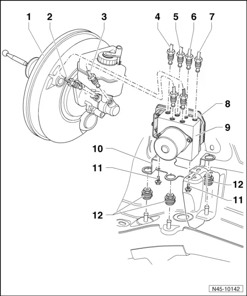
1 - Brake Booster
- Removing and installing, refer to → Chapter "Brake Booster, Removing and Installing".
2 - Brake Line
- Master brake cylinder/primary piston circuit to hydraulic control unit
- Identification: 6.5 mm diameter and union bolt with long thread M12x1
- Marked on hydraulic unit with "HZ1"
- Tightening specification, refer to → Fig. "Brake Lines on the Brake Master Cylinder - Tightening Specification".
3 - Brake Line
- Master brake cylinder/secondary piston circuit to hydraulic unit
- Identification: 6.5 mm diameter and union bolt with long thread M12x1
- Marked on hydraulic unit with "HZ2"
- Tightening specification, refer to → Fig. "Brake Lines on the Brake Master Cylinder - Tightening Specification".
4 - Brake Line
- To the right front brake caliper
- Identification: 5.25 mm diameter and union bolt with thread M10x1
- Marked on hydraulic unit with "VR"
- Tightening specification and sequence → Fig. "Brake Lines on the Hydraulic Unit - Tightening Specification and Sequence".
5 - Brake Line
- To the left rear brake caliper
- Identification: 5.25 mm and union bolt with short thread M12x1
- Marked on hydraulic unit with "HL"
- Tightening specification and sequence, refer to → Fig. "Brake Lines on the Hydraulic Unit - Tightening Specification and Sequence".
6 - Brake Line
- To the right rear brake caliper
- Identification: 5.25 mm diameter and union bolt with thread M10x1
- Marked on hydraulic unit with "HR"
- Tightening specification and sequence, refer to → Fig. "Brake Lines on the Hydraulic Unit - Tightening Specification and Sequence".
7 - Brake Line
- To the left front brake caliper
- Identification: 5.25 mm and union bolt with short thread M12x1
- Marked on hydraulic unit with "VL"
- Tightening specification and sequence, refer to → Fig. "Brake Lines on the Hydraulic Unit - Tightening Specification and Sequence".
8 - ABS Control Module -J104-
- Separating the control module and hydraulic unit is not possible
- With integrated Brake Pressure Sensor 1 -G201-
- Removing and installing, refer to → Chapter "ABS Control Module -J104-/ABS Hydraulic Unit -N55-, Removing and Installing".
9 - ABS Hydraulic Unit -N55-
- Separating the control module and hydraulic unit is not possible
- Removing and installing, refer to → Chapter "ABS Control Module -J104-/ABS Hydraulic Unit -N55-, Removing and Installing".
10 - Bracket
11 - Bolt
- 8 Nm
12 - Rubber Insulation
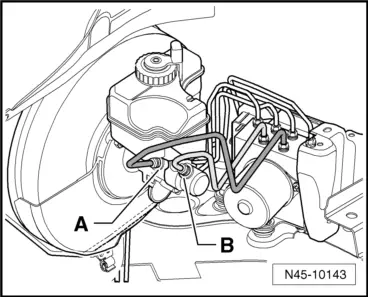
Brake Lines on the Brake Master Cylinder - Tightening Specification
- Tighten the brake lines -A and B- to 14 Nm by counterholding the brake lines.
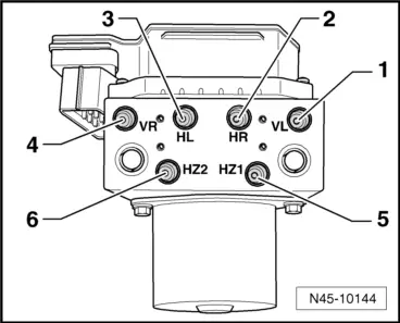
Brake Lines on the Hydraulic Unit - Tightening Specification and Sequence
- Tighten the brake lines in the sequence -1 to 6- to 14 Nm by counterholding the brake lines -5 and 6-.
ABS Control Module -J104-/ABS Hydraulic Unit -N55-, Removing and Installing
 Note
Note
If the control module is replaced, select the "Replace" function in "Guided Functions" on the control module, refer to → Vehicle diagnostic tester.
Special tools and workshop equipment required
- Brake Pedal Actuator -VAG1869/2-.
- Container -1- from the Brake Charger/Bleeder Unit -VAS5234-
- Plugs from Repair Kit -1H0 698 311 A-
1 - Transport protection for valve domes (foam)
2 - Sealing plugs M10
3 - Sealing plugs M12
Removing
 WARNING
Do not bend the brake lines near the hydraulic unit.
- Get the coding from the control module mount and write it down, refer to Vehicle Diagnostic Tester.
Audi Q3
- Remove the battery and the battery tray, refer to → Electrical Equipment; Rep. Gr.27; Battery; Battery Tray, Removing and Installing.
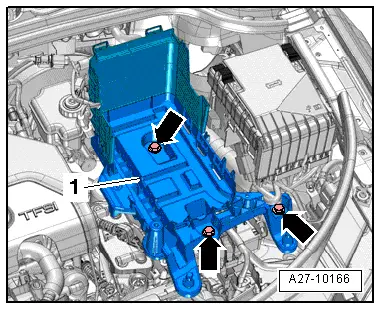
Audi RS Q3
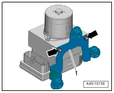
- Remove the air filter housing, refer to → Engine Mechanical, Fuel Injection and Ignition; Rep. Gr.24; Air Filter; Air Filter Housing, Removing and Installing.
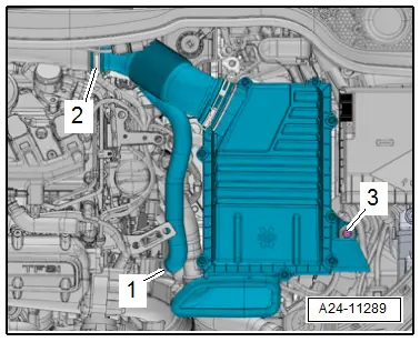
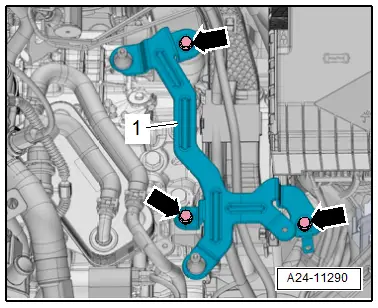
- Remove the bolts -arrows- and remove the bracket -1- for the air filter housing.
Continuation for All Vehicles
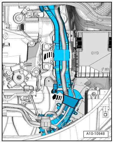
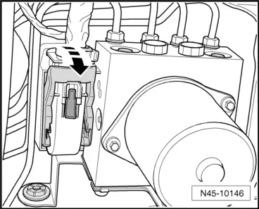
- Open the bracket for the wiring guide in direction of -arrows- and push the wires aside.
- Remove the wiring guide.
- Push the red locking slide downward in direction of -arrow-.
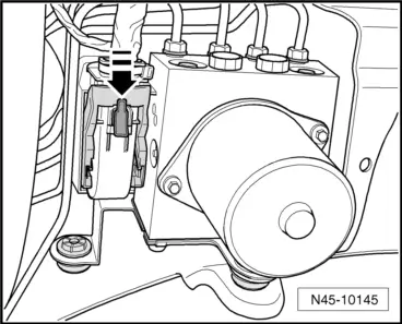
- Release the connector -arrow- and disconnect it.
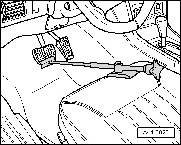
- Insert the Brake Pedal Actuator -VAG1869/2- between the brake pedal and driver seat. Preload the brake pedal at least 60 mm.
 Note
Note
By doing this, the valves in the brake master cylinder are closed and the brake fluid reservoir does not run empty.
 WARNING
Risk of skin irritation.
To prevent skin contact with brake fluid, wear chemical resistant protective gloves.
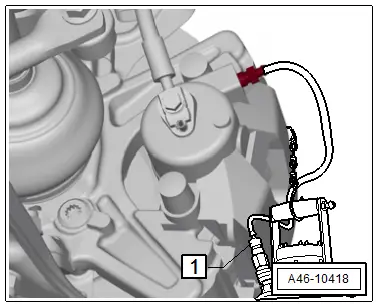
- Remove the protective cap from the left front brake caliper bleeder screw.
- Place the container bleed hose -1- on the bleeder screw.
- Open the bleeder screw to reduce the pressure in the hydraulic system.
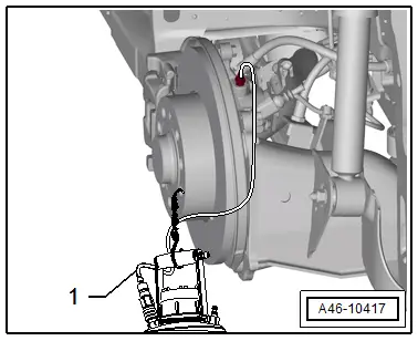
 Note
Note
The 1LJ 1ZD brakes are illustrated.
- Remove the protective cap from the left rear brake caliper bleeder screw.
- Place the container bleed hose -1- on the bleeder screw.
- Open the bleeder screw to reduce the pressure in the hydraulic system.
- Close the left front and left rear bleeder screws.
 Note
Note
Do not remove the Brake Pedal Actuator -VAG1869/2-.
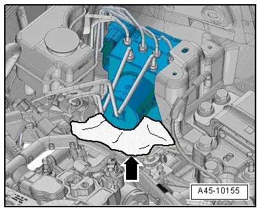
- Place sufficient lint-free cloths -arrow- under the control module and hydraulic unit.
 Caution
Make sure that brake fluid does not come in contact with the terminals.
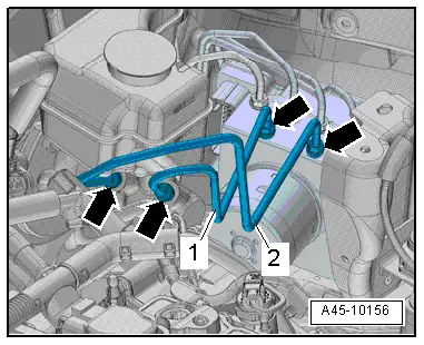
- Remove the union bolts -arrows- and remove the brake lines -1 and 2-.
- Immediately seal off the brake lines and the threaded holes with the plugs from Repair Kit -1H0 698 311 A-.
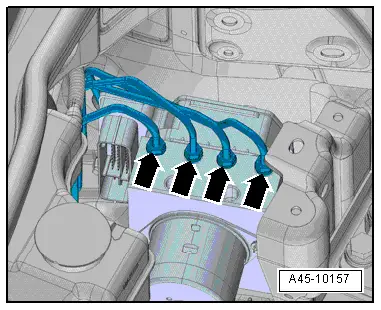
- Mark the remaining brake lines to the brake calipers, then remove and seal them.
- Remove the union bolts, tie the brake lines upward and seal them.
- Immediately seal off the brake lines and the threaded holes with the plugs from Repair Kit -1H0 698 311 A-.
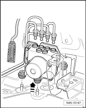
- Lift the hydraulic unit with the control module upward and out of the rubber buffers -arrow-.
- Remove the bolts -arrows- and the bracket -1-.
Installing
Install in reverse order of removal. Note the following:
- Remove the bracket.
- Press the ABS Hydraulic Unit -N55- with the ABS Control Module -J104- into the rubber buffers.
- Tighten the brake lines while paying attention to the sequence and tightening specifications.
- Remove the Brake Pedal Actuator -VAG1869/2-.
 Note
Note
- Do not remove sealing plugs at new hydraulic unit until the corresponding brake line is about to be installed.
- If the sealing plugs are removed too early, brake fluid can escape and unit may not be sufficiently filled or adequately bled.
- When installing the hydraulic unit, make sure the damper rubber is not pushed out of the bracket. The damper rubber must lie on the longitudinal member cover plate.
Tightening Specifications
- Battery tray and battery, refer to → Electrical Equipment; Rep. Gr.27; Battery; Overview - Battery.
READ NEXT:
 Sensors
Overview - Front Axle Speed Sensor
1 - Wheel Speed Sensor
Right Front ABS Wheel Speed Sensor -G45-/Left Front ABS Wheel Speed
Sensor -G47-
Removing and installing, refer to
→&
Overview - Front Brakes
Overview - Front Brakes, 1LJ 1ZD Brakes
1 - Bolt
12 Nm
2 - Brake Rotor
Allocation, refer to the Parts Catalog.
Dimensions, refer to
→ Chapter "Brakes
SEE MORE:
Steering Column Switch Module, Removing and Installing
Steering Column Switch Module, Removing and Installing, with Mechanical
Ignition Lock
Removing
- Adjust steering wheel downward and to rear as far as
possible, use entire adjustment range of steering column
adjustment for this.
- Remove the driver airbag. Refer to
→ Body
Speaker Ambient Lighting Bulb 1 and 2 -L211-/-L212-, Removing and Installing
Speaker Ambient Lighting Bulb 1 -L211-, Removing and Installing, Front
Door
Removing
- Remove the front door trim panel. Refer to
→ Body Interior; Rep. Gr.70; Front Door Trim Panels; Front Door
Trim Panel, Removing and Installing.
- Disconnect the connector -4-.
-
