Audi Q3: Parking Brake
Overview - Parking Brake
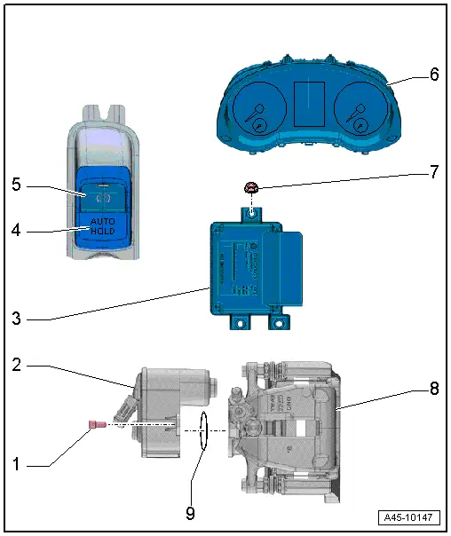
1 - Bolt
- Tightening specification, refer to item-14-.
2 - Parking Brake Motor
- Left Parking Brake Motor -V282-, Right Parking Brake Motor -V283-
- Removing and installing, refer to → Chapter "Left/Right Parking Brake Motor -V282-/-V283-, Removing and Installing".
3 - Electromechanical Parking Brake Control Module -J540-
- Removing and installing, refer to → Chapter "Electromechanical Parking Brake Control Module -J540-, Removing and Installing".
4 - -AUTO HOLD- Button -E540-
- With -AUTO HOLD- Indicator Lamp -K237-
- Component location: inside the center console
5 - Electromechanical Parking Brake Button -E538-
- With Electromechanical Parking Brake Indicator Lamp -K213-
- Component location: inside the center console
6 - Instrument Cluster
- With
- Brake System Indicator Lamp -K118-
- Electromechanical Parking Brake Indicator Lamp -K213-
7 - Nut
- 2.5 Nm
8 - Rear Brake Caliper
9 - Seal
Electromechanical Parking Brake Control Module -J540-, Removing and Installing
The Transverse Acceleration Sensor -G200-, the Rotation Rate Sensor -G202- and the Longitudinal Acceleration Sensor -G251- are also integrated in the Electromechanical Parking Brake Control Module -J540- housing.
 Note
Note
If the control module is replaced, select the "Replace" function in "Guided Functions" on the control module, refer to Vehicle Diagnostic Tester.
Removing
- Remove the center console, refer to → Body Interior; Rep. Gr.68; Center Console; Center Console, Removing and Installing.
- If installed: Remove the rear air guide channel, refer to → Heating, Ventilation and Air Conditioning; Rep. Gr.87; Air Routing; Air Distribution Channels, Removing and Installing.
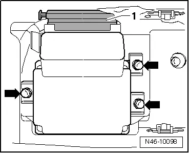
- Disconnect the connector -1-.
- Remove the nuts -arrows- and then remove the Electromechanical Parking Brake Control Module -J540-.
Installing
Install in reverse order of removal. Note the following:
 Caution
If the Electromechanical Parking Brake Control Module -J540- has fallen onto a hard surface or shows any signs of damage, it must not be installed.
- Make sure it is seated without tension on the bracket.
- Install the rear air guide channel, refer to → Heating, Ventilation and Air Conditioning; Rep. Gr.87; Air Routing; Air Distribution Channels, Removing and Installing.
- Install the center console, refer to → Body Interior; Rep. Gr.68; Center Console; Center Console, Removing and Installing.
Left/Right Parking Brake Motor -V282-/-V283-, Removing and Installing
Special tools and workshop equipment required
- Vehicle Diagnostic Tester
- Torque Wrench 1331 5-50Nm -VAG1331-
Removing
- Release the parking brake.
- Turn off the ignition.
 Note
Note
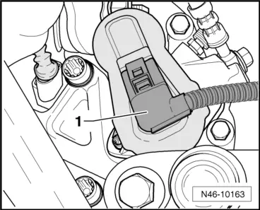
Ignition must be switched off for at least 30 seconds before disconnecting the connector.
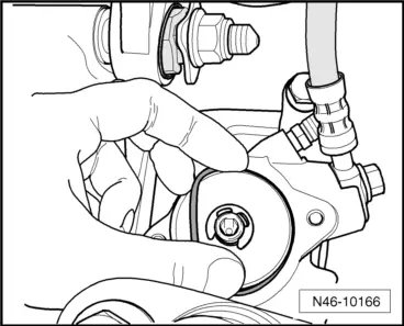
- Disconnect the connector -1- from the parking brake motor.
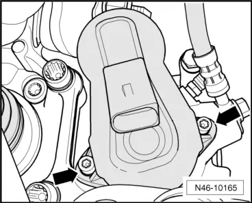
- Remove the bolts -arrows- for the parking brake motor.
- Remove the parking brake motor from the brake caliper.
- Remove the seal.
- Clean the parking brake motor ring groove and contact surface.
Installing
Install in reverse order of removal. Note the following:
- The ring groove and contact surface of the parking brake motor must not be damaged.
- Lightly coat the new seal with brake fluid and install it.
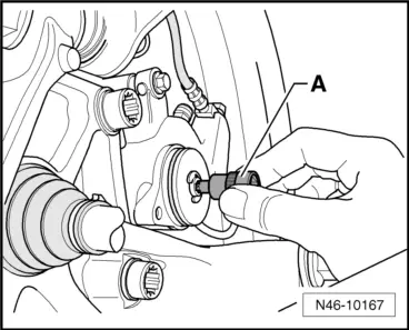
- Using an 8 mm internal multi-point socket -A-, turn the spindle back a little until the parking brake motor can be positioned correctly.
 Caution
Do not remove the gasket when assembling the parking brake motor.
- Rotate the parking brake motor until the bolt hole and threads are aligned.
- The parking brake motor must be flush with the brake caliper. It must not be tightened against the brake caliper with bolts.
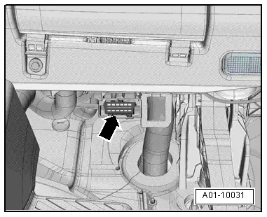
- Connect the Vehicle Diagnostic Tester to the vehicle Data Link Connector (DLC) with the ignition switched off -arrow-.
- Turn on the ignition.
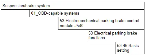
- After entering the VIN, select Guided Functions.
- Basic Setting, Performing
- Continue to follow the instructions in the Vehicle Diagnostic Tester display.
READ NEXT:
 Brake Pedal
Overview - Brake Pedal
1 - Mounting Bracket
Removing and installing, refer to
→ Chapter "Mounting Bracket, Removing and Installing".
2 - Nut
25 Nm
Alw
Overview - Front Brake Caliper
Overview - Front Brake Caliper, Single-Piston Brake
1 - Protective Cap
Place on the bleed screw
2 - Bleeder Screw
10 Nm
Before installing, lightly coat the thr
SEE MORE:
Folding the outer backrests
Applies to: vehicles with folding backrests
Fig.72 Rear bench seat: loop
The rear seat backrests can be folded forward either
separately or together.
Observe the safety precautions.
If necessary, slide the rear bench seat back.
To fold the backrest forward, pull the strap 1
in the direction of
Wheel and Tire Guide
Audi Q3, Type 8U
This is the Wheel and Tire Guide for the Following Model:
"Audi Q3 / RS Q3".
Play Close Attention to the corresponding Notes and Cautions As Well As the
Comments in the Document.
Note
Inner diameter 57 mm, hole circle 112 mm, 5 wheel bolts,
tightening specification
