Audi Q3: Rear Window Defogger
Rear Window Defogger -Z1-, Checking, Vehicles with Manual Climate Control System (Heater without A/C System)
Procedure
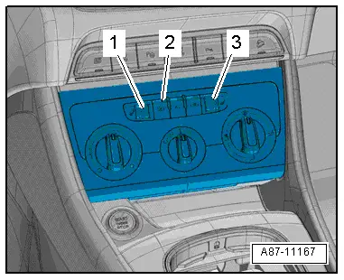
The rear window defogger is switched on via the button -2- on the A/C Control Module -J301- (the Heater Control Module -J65-) control head.
 Note
Note
- By pressing the button -2-, the A/C Control Module -J301- (the Heater Control Module -J65-) control head activates the Vehicle Electrical System Control Module -J519- via the data bus when the ignition is switched on. As soon as the Vehicle Electrical System Control Module -J519- switches on the rear window defroster (only when the engine is running), the indicator lamp in the button -2- comes on (the Electrical System Control Module -J519- sends the return message via the data bus. The rear window defogger is switched off by pressing button again and by switching ignition off. Refer to the Owner's Manual and → Wiring diagrams, Troubleshooting & Component locations.
- If the measured voltage at terminal "30" at the Vehicle Electrical System Control Module -J519- falls below a value stored in the Vehicle Electrical System Control Module -J519- or the A/C Control Module -J301- (Heater Control Module -J65-) control head, the rear window defogger is switched off completely (or the output is reduced), therefore reducing the load on the Generator -C-. Refer to Vehicle Diagnostic Tester in the "Guided Fault Finding" function.
- The Rear Window Defogger -Z1- is only activated by the Vehicle Electrical System Control Module -J519- when the engine is running. When the engine is off, there is no activation and no return message from the Vehicle Electrical System Control Module -J519-. The Light Emitting Diode (LED) in the button -2- does not come on, or will go out shortly after the button is pushed. Refer to the Owner's Manual and → Wiring diagrams, Troubleshooting & Component locations.
- If the Rear Window Defogger -Z1- activation must be switched off due to insufficient voltage, the indicator lamp in the rear window defogger button -2- in the A/C Control Module -J301- (the Heater Control Module -J65-) control head remains switched on. Should it take longer to shut off, the Vehicle Electrical System Control Module -J519- switches off the indicator lamp via a message.
- The Guided Fault Finding "Read measured values" function for the A/C Control Module -J301- (the Heater Control Module -J65-) control head shows that the rear window defogger is switched on or why it was not activated even though there was a request. Refer to Vehicle Diagnostic Tester in the "Guided Fault Finding" function.
- The function test for the rear window defogger activation is described. Refer to Vehicle Diagnostic Tester in the "Guided Fault Finding" function.
- The Rear Window Defogger -Z1- switches itself off when the outside air temperature is higher than 0 ºC (32 ºF) the operating time stored in the Vehicle Electrical System Control Module -J519- (approximately 10 minutes) by the Vehicle Electrical System Control Module -J519-.
- The Rear Window Defogger -Z1- stays switched on with outside temperatures less than 0 ºC (32 ºF) until ignition is switched off (it can be switched on and off manually at any time). If the temperature becomes greater than 0 ºC (32 ºF) during a driving period, the Rear Window Defogger -Z1- is switched off after the operating time stored in the Vehicle Electrical System Control Module -J519- has elapsed (approximately 10 minutes).
- For vehicles with a Start/Stop System, the rear window defogger can be switched off for the time in which the stop function is active (to protect the Battery -A-). However, the setting for the Rear Window Defogger -Z1- actuation remains stored. After the engine was started again via the start function, the rear window defogger is switched on again. Refer to Vehicle Diagnostic Tester in the "Guided Fault Finding" function.
Rear Window Defogger -Z1-, Checking, Vehicles with Automatic Climate Control System
Procedure
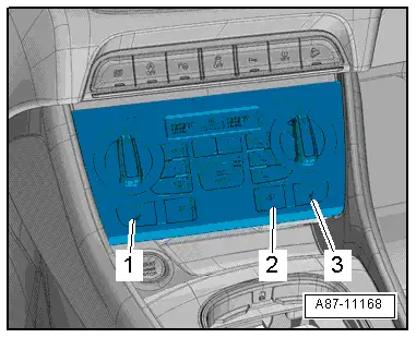
The rear window defogger is switched on via the button -2- on the Climatronic Control Module -J255- control head.
 Note
Note
- By pressing the button -2-, the Climatronic Control Module -J255- control head activates the Vehicle Electrical System Control Module -J519- via the data bus when the ignition is switched on. As soon as the Vehicle Electrical System Control Module -J519- switches on the rear window defroster (only when the engine is running), the indicator lamp in the button -2- comes on (the Vehicle Electrical System Control Module -J519- sends the return message via the data bus. The rear window defogger is switched off by pressing button -2- again and by switching the ignition off. Refer to the Owner's Manual and → Wiring diagrams, Troubleshooting & Component locations.
- If there is a condition that the rear window defogger cannot be switched on (short circuit in the connection to the rear window, interruption in the power supply to the Climatronic Control Module -J255- control head or to the Vehicle Electrical System Control Module -J519-), this will be stored as a fault in the respective control module. Refer to Vehicle Diagnostic Tester in the "Guided Fault Finding" function.
- If the measured voltage on the Vehicle Electrical System Control Module -J519- to terminal "30" falls below a value stored in the Vehicle Electrical System Control Module -J519-, the rear window defogger will be switched off completely (or the output will be reduced) to relieve the load on the Generator -C-. Refer to Vehicle Diagnostic Tester in the "Guided Fault Finding" function.
- The Vehicle Electrical System Control Module -J519- only activates the rear window defogger when the engine is running. If the engine is not running, there is no return message from the Vehicle Electrical System Control Module -J519- and the LED in the button -2- for the Climatronic Control Module -J255- goes out again for a short time after pressing.
- If the Rear Window Defogger -Z1- activation must be switched off due to insufficient voltage, the indicator lamp in the rear window defogger button in the Climatronic Control Module -J255- remains switched on. If it takes longer than approximately 150 seconds to switch off, the Climatronic Control Module -J255- will switch off the indicator lamp.
- The Guided Fault Finding "Read measured values" function for the Climatronic Control Module -J255- control head shows that the rear window defogger is switched on or why it was not activated even though there was a request. Refer to Vehicle Diagnostic Tester in the "Guided Fault Finding" function.
- The function test for the rear window defogger activation is described. Refer to Vehicle Diagnostic Tester in the "Guided Fault Finding" function.
- The Rear Window Defogger -Z1- switches itself off when the outside air temperature is higher than 0 ºC (32 ºF) after the operating time stored in the Vehicle Electrical System Control Module -J519- (approximately 10 minutes) by the Vehicle Electrical System Control Module -J519-.
- The Rear Window Defogger -Z1- stays switched on with outside temperatures less than 0 ºC (32 ºF) until ignition is switched off (it can be switched on and off manually at any time). If the temperature becomes greater than 0 ºC (32 ºF) uring a driving period, the Rear Window Defogger -Z1- is switched off after the operating time stored in the Vehicle Electrical System Control Module -J519- has elapsed (approximately 10 minutes).
- For vehicles with a Start/Stop System, the rear window defogger can be switched off for the time in which the stop function is active (to protect the Battery -A-). However, the setting for the Rear Window Defogger -Z1- actuation remains stored. After the engine was started again via the start function, the rear window defogger is switched on again. Refer to Vehicle Diagnostic Tester in the "Guided Fault Finding" function.
Coolant Fan
- There are different versions. Refer to the Parts Catalog.
- The Climatronic Control Module -J255- or the A/C Control Module -J301- control head transmits the request to switch on the A/C system operation (to cool the condenser) to the engine control module via the data bus. The engine control module then activates the fan(s) ( Coolant Fan -V7- and Coolant Fan 2 -V177-) directly or via the Coolant Fan Control Module -J293-. Refer to → Rep. Gr.19; Radiator/Coolant Fan; Radiator, Removing and Installing and → Wiring diagrams, Troubleshooting & Component locations.
- To check the activation of the coolant fans for the Climatronic Control Module -J255-, refer to Vehicle Diagnostic Tester in the "Guided Fault Finding" function.
- The respective engine control module continuously switches the Coolant Fan -V7- and the Coolant Fan 2 -V177- (directly or via the Coolant Fan Control Module -J293-) to the desired output (depending on the engine type). Refer to Vehicle Diagnostic Tester in the "Guided Fault Finding" function and → Wiring diagrams, Troubleshooting & Component locations.
Outside Air Temperature Display -G106-
- It is a component of the Instrument Cluster Control Module -J285-. Refer to → Electrical Equipment; Rep. Gr.90; Instrument Cluster; Overview - Instrument Cluster.
- If the temperature display if faulty, check the measured value of the Outside Air Temperature Sensor -G17-. Refer to Vehicle Diagnostic Tester in the "Guided Fault Finding" function, A/C system, instrument cluster "Read measured values".
 Note
Note
If there is a faulty measured value for the Outside Air Temperature Sensor -G17-, complaints may arise regarding the Air Conditioning (A/C) system regulation. The Climatronic Control Module -J255- or the A/C Control Module -J301- control head does not activate the A/C compressor when the exterior temperature is too low. Refer to Vehicle Diagnostic Tester in the "Guided Fault Finding" function.
READ NEXT:
 A/C Compressor Regulator Valve -N280-, Checking Switch-On Signal
Special tools and workshop equipment
required
Vehicle Diagnostic Tester
Connector Test Set -VAG1594D-
Probe -VAS5051/8-
Test Sequence
- Remove the noise insulation. Refer to
→&n
Safety Precautions
Handling Refrigerant Safety Precautions
The assemblies and piping system of the air conditioner are
filled with the following refrigerant:
1.1.1.2 Tetrafluorethane (CF3-CH2F
or CH2F-CF3)
Curren
SEE MORE:
A-Pillar Trim Panel, Removing and Installing
Special tools and workshop equipment
required
Pry Lever -80-200-
Omega Clip Tool -T40280-
Removing
WARNING
Follow all safety precautions when working with
pyrotechnic components. Refer to
→ Chapter "Pyrotechnic Components Safety Precautions".
- Remove the inst
Drive Axle, Removing and Installing, Left Drive Axle with CV Joint, Inserted
with Inner Splines
Special tools and workshop equipment
required
Puller - Driveshaft -T10382-
Torque Wrench 1332 40-200Nm -VAG1332-
Slide Hammer Set -VW771-
Removing
- Loosen the drive axle threaded connection on the wheel side.
Refer to
→ Chapter "Drive Axle Threaded Connection, Loosenin
