Audi Q3: Drive Axle, Removing and Installing, Left Drive Axle with CV Joint, Inserted with Inner Splines
Special tools and workshop equipment required
- Puller - Driveshaft -T10382-
- Torque Wrench 1332 40-200Nm -VAG1332-
- Slide Hammer Set -VW771-
Removing
- Loosen the drive axle threaded connection on the wheel side. Refer to → Chapter "Drive Axle Threaded Connection, Loosening and Tightening".
- Remove the front wheel. Refer to → Chapter "Wheels and Tires".
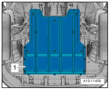
- Remove the noise insulation -1-. Refer to → Body Exterior; Rep. Gr.66; Noise Insulation; Noise Insulation, Removing and Installing.
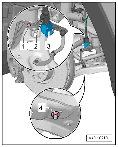
- If installed, disconnect the vehicle level control system sensor coupling rod from the control arm by removing the nut -4-.
- Remove the right drive axle heat shield. Refer to → Chapter "Drive Axle Heat Shield, Removing and Installing".
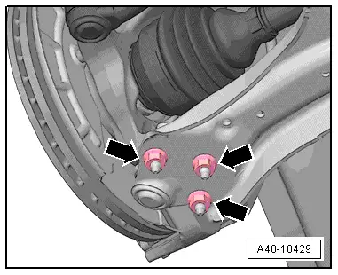
- Remove the nuts -arrows-.
- Remove the control arm from the ball joint.
 Note
Note
Pay attention during the assembly work that the ball joint rubber boot is not damaged. If necessary protect the ball joint rubber boot against damage.
- Pivot the suspension strut outward, while doing so push the drive axle out of the wheel bearing unit.
- Slide outer joint out of wheel hub by hand.
- Secure the drive axle to keep it from falling down.
 Note
Note
In order to remove the driveshaft from the transmission using the Puller - Driveshaft -T10382-, the suspension strut and all its components must be pulled to the back. Be careful not to damage any parts, for example, brake hose, ABS line.
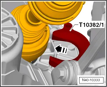
- Align the Puller - Driveshaft -T10382-.
- For the CV joint -1-, the opening -arrow- in the Puller - Driveshaft - Removing Plate -T10382/1- must face the Puller - Driveshaft - Spindles -T10382/2-.
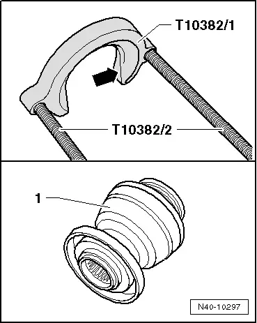
- Place the Puller - Driveshaft - Removing Plate -T10382/1- behind the CV joint -1-.
- The opening slides in the direction of -arrow-, the Puller - Driveshaft - Removing Plate -T10382/1- must face the CV joint -1-.
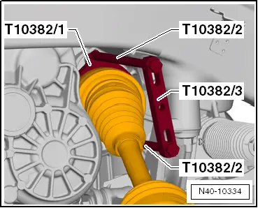
- Install the Puller - Driveshaft - Spindles -T10382/2- and Traverse -T10382/3- on the Puller - Driveshaft - Removing Plate -T10382/1-.
- Install the Slide Hammer Set -VW771- on the Traverse -T10382/3-.
- Remove the drive axle with a few hits on the Slide Hammer Set -VW771-.
- Remove the drive axle from the vehicle.
Installing
Installation is reverse of removal, noting the following:
- Lightly coat the splines on the outer joint with assembly paste before installing the outer joint into the wheel hub. Refer to the Parts Catalog.
Remove any paint residue and/or corrosion in threads/splines of outer joint.
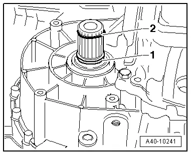
- Install a new seal -1- and locking ring -2- into the groove on the stub shaft on the transmission.
- Apply approximately 2 g of grease all around the splines on the transmission. Refer to the Parts Catalog.
- Bring outer and inner splines of the transmission and CV joint into engagement.
- Grab the drive axle by hand and push it into the CV joint up to the stop.
- Now push the CV joint with one jerk onto the transmission stub shaft.
 Note
Note
- If it is difficult to install the drive axle even though the splines are positioned correctly, then slide it in the slip joint.
- Never use a hammer or mallet!
- Make sure the CV joint is seated securely, to do this pull the CV joint against the resistance of the securing ring.
 Caution
When checking, only pull on the CV joint piece and not on the drive axle.
- Install the outer joint as far as possible into the wheel hub splines.
 Note
Note
Make sure the ball joint boot is not damaged or twisted.
- Tighten the driveshaft to wheel hub threaded connection. Refer to → Chapter "Drive Axle Threaded Connection, Loosening and Tightening".
- Install the front wheel. Refer to → Chapter "Wheels and Tires".
- On vehicles with electronically controlled damping, perform the function "Adapt the control position" with the Vehicle Diagnosis Tester.
- If the control position was reprogrammed and if the vehicle has lane assist, then it will then be necessary to calibrate the driver assistance systems front camera. Refer to → Chapter "Driver Assistance Systems Front Camera, Calibrating".
- On vehicles with level control system sensor, perform headlamp basic setting. Refer to → Electrical Equipment; Rep. Gr.94; Headlamp, Adjusting.
READ NEXT:
 Drive Axle, Removing and Installing, Right Drive Axle with CV Joint,
Inserted with Inner Splines
Drive Axle, Removing and Installing, Right Drive Axle with CV Joint,
Inserted with Inner Splines
Special tools and workshop equipment
required
Slide Hammer Set -VW771-
Tensioning Strap -T10038-
Puller - Driveshaft -T10382-
Torque Wrench 1332 40-200Nm -VAG1332-
Digital Torque Wrench
Drive Axle Threaded Connection, Loosening and Tightening
Special tools and workshop equipment
required
Socket AF 24 mm -T10361A-
Digital Torque Wrench -VAG1756A-
The wheel bearing must not be under a load while the drive
axle threaded connectio
CV Joint, Servicing, Drive Axle with CV Joint VL107
Special tools and workshop equipment
required
Clamping Pliers -VAG1682A-
Circlip Pliers -VW161A-
Press Plate -VW401-
Press Plate -VW402-
Press Piece - Rod -VW408A-
CV Joint Press Sleev
SEE MORE:
Check Valve, Checking
Check valve is removed, refer to
→ Chapter "Check Valve, Removing and Installing".
Note
The check valve is installed directly in front of the vacuum
pump.
Valve must allow air to flow in direction of arrow.
Valve must remain closed in opposite direction.
Overview - Generator, Valeo through MY 2000
1 - Generator
2 - Voltage Regulator
Removing:
Remove the nuts -5- and the cover
-4-.
Remove the bolt -6- and the nuts
-7- and remove the voltage regulator.
Carbon brushes wear limit: 5 mm
3 - Protective Cap
4 - Cover
5 - N
