Audi Q3: Check Valve, Checking
- Check valve is removed, refer to → Chapter "Check Valve, Removing and Installing".
 Note
Note
The check valve is installed directly in front of the vacuum pump.
- Valve must allow air to flow in direction of arrow.
- Valve must remain closed in opposite direction.
 Note
Note
- Make sure it is installed in the correct position
- The flow direction arrow faces the vacuum pump.
Check Valve, Removing and Installing
 Note
Note
- The check valve is installed directly in front of the vacuum pump.
- The vacuum pump does not have to be removed.
Removing
Audi Q3:
- Open the clamp on the vacuum hose using suitable pliers.
- Remove the vacuum hose from the Brake System Vacuum Pump -V192-.
 Caution
Be careful not to damage the vacuum hose. Replace the vacuum hose if damaged.
Audi RS Q3:
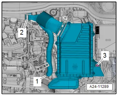
- Remove the air filter housing, refer to → Engine Mechanical, Fuel Injection and Ignition; Rep. Gr.24; Air Filter; Air Filter Housing, Removing and Installing.

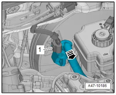
- Disconnect the connector -1-.
- Remove the vacuum hose from the brake booster -arrow-.

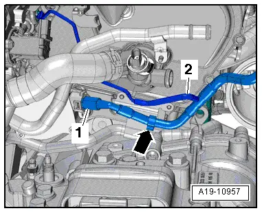
- Remove the vacuum hose -2-.
- Free up the vacuum hose -1--arrow-, pull it out of the brake booster vacuum pump and remove it.
 Caution
Be careful not to damage the vacuum hose. Replace the vacuum hose if damaged.
Installing
 Note
Note
Coat the check valve and the vacuum hose lightly with some water, not oil, to make them easier to install.
- Slide the new clamp over the vacuum hose.


