Audi Q3: Brake Lines
Separating Points
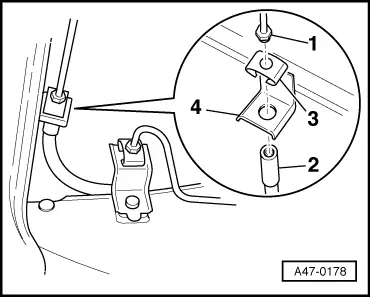
Brake Line on the Underbody
1 - Brake line
2 - Brake hose
3 - Spring
4 - Brake hose bracket
Tightening Specifications
- Refer to item -10-, item -16-.
Brake Line to Brake Line
- Counterhold the union nut -1- when tightening the union bolt -2-.
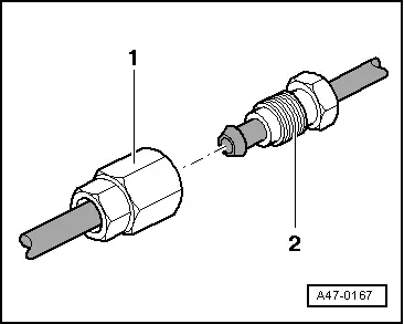
Tightening specification
- 14 Nm
Brake Line Routing
- Brakes and brake lines are delivered as ready-to-install replacement parts.
- Secure brakes and brake lines at original fastening points when installing.
 WARNING
Risk of accident!
Make sure the brakes are working correctly before driving the vehicle.
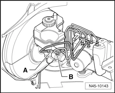
Brake Lines on the Brake Master Cylinder
- Tightening specifications, refer to → Fig. "Brake Lines on the Brake Master Cylinder - Tightening Specification".
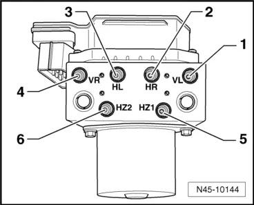
Brake Lines on the Hydraulic Unit
- Tightening specifications, refer to → Fig. "Brake Lines on the Hydraulic Unit - Tightening Specification and Sequence".
Brake Lines, Repairing
Flare the brake lines using Brake Line Tool Kit -VAS6056- without damaging coating. In this way, brake lines can be inexpensively partially replaced in certain cases.
 Caution
Danger of damaging the brake lines.
- Using the Brake Line Kit VAG1356 is not permitted because of the coating and diameter of the black brake lines.
- Brake lines must not be bent more than a maximum of 90º, otherwise they kink or deform, which causes unacceptable constriction in the line.
 Note
Note
- Disconnect brake lines preferably at underbody.
- Position of intermediate pieces should be selected so that they cannot rub against moving parts.
- Do not lubricate spindle, clean only with mineral spirits.
Special tools and workshop equipment required
- Brake Line Tool Kit -VAS6056-
Listing of Individual Tools
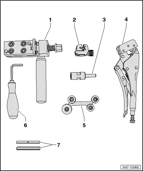
1 - Brake Line Tool Kit - Flanging Tool -VAS6056/1- (including Clamp Jaws -VAS6056/6-)
2 - Brake Line Tool Kit - Pipe Cutter -VAS6056/2-
3 - Brake Line Tool Kit - Brake Line Scraper -VAS6056/3-
- The threaded pins (in shaft and at sides) are set and must not be adjusted!
4 - Brake Line Tool Kit - Line Grips -VAS6056/4-
5 - Brake Line Tool Kit - Pipe Bending Tool - VAS6056/5-
6 - SW6 Angle Screwdriver
7 - Clamp Jaws -VAS 6056/6-, -VAS6056/7-
Flaring Tool (including flaring jaws VAS6056/6)
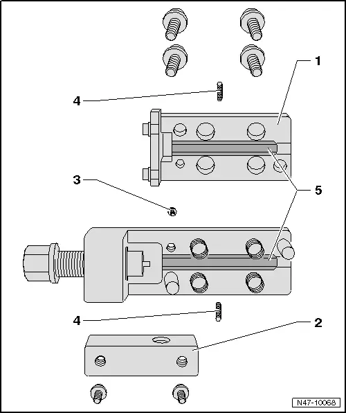
1 - Upper Part of Flaring Tool
- Remove to change Clamp Jaws
2 - Hand Grip Mount
- Must be removed to reach the upper section retaining bolt
3 - Screw
- For upper part of flaring tool
4 - Clamp Jaws Threaded Pins
- Center and hold the Clamp Jaws
- 2 mm hex socket head
5 - Clamp Jaws
- Various
- Assembly instructions → Fig.
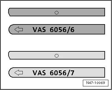
Flaring Jaws Assembly Instructions:
- VAS 6056/6 (dark) for black brake lines
- VAS 6056/7 (light) for green brake lines
 Note
Note
The arrow on the rounded side of the flaring jaws must face toward edge of housing and the straight side of the flaring jaws must be installed toward spindle, otherwise flared head will not be formed correctly.
Instructions
- Remove the affected brake line at brake caliper or wheel brake cylinder and collect escaping brake fluid and dispose of it correctly.
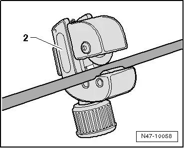
- Disconnect brake line at appropriate location (straight, accessible part) with line cutter -2-.
- Remove the piece to be exchanged.
- Lubricate brake line surface.
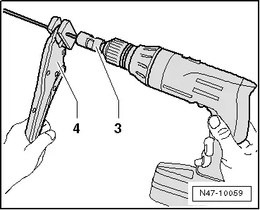
- Clamp brake line in self-grip pliers -4- so that 50 mm of the plastic clamping jaws show.
- Clamp the shearing tool -3- in a drill and place it on the brake line.
- Shear the coating from the brake line at a slow drill RPM and with light pressure against the line.
The length of the sheared-off portion is determined by the stop in the shearing tool.
- Remove the shearing tool from the brake line and remove the shearing remains.
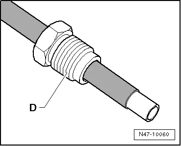
- Remove locking pliers and union bolt -D- from brake line.
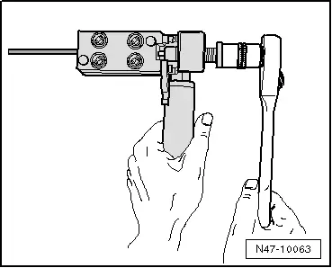
- Slide the brake line -B- against the stop -A- in flaring tool.
 Note
Note
Brake line must contact stop when hex socket heat screws are tightened, otherwise the flared head will not be formed correctly.
C - Long reach special wrench
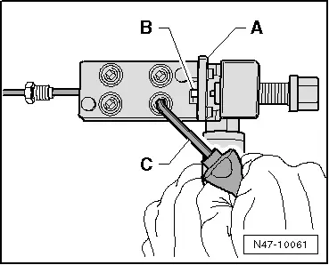
- Pretension the brake line inside the flaring unit until the brake line can no longer be moved. Fold stop -A- up and tighten hex socket head screws diagonally with long reach special wrench.
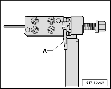
- Turn the spindle to stop in flaring tool.
- Turn the spindle back.
- Loosen the hex socket head screws diagonally.
- Remove the brake line from the flaring tool, clean and check the brake line and the flared head.
- Quickly rinse the part of the brake line still in the vehicle by connecting the Brake Charger/Bleeder Unit -VAS5234-.
- Connect the container hose to the flared head of the brake line and let the Brake Charger/Bleeder Unit -VAS5234- run briefly until some brake fluid runs through.
- Clean the brake line with compressed air.
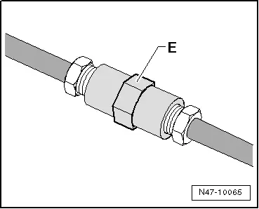
- Join brake lines with connecting piece -E-.
- Assemble brake line.
- Then bleed the brake system, refer to → Chapter "Hydraulic System, Bleeding".
READ NEXT:
 Hydraulic System
Brake Fluid General Information
Brake fluid is hygroscopic, for example it has the ability
to absorb water and moisture from the air.
If water has been absorbed, the boiling point will drop, for
Special Tools
Special tools and workshop equipment
required
Piston Resetting Tool -T10145-
Piston Resetting Tool - Cap /6 -T10146/6- from Piston
Resetting Tool - Caps /1,/2,/3,/4,/5 -T10146-
SEE MORE:
Cockpit
Fig. 1 Cockpit
Door handle
Central locking switch
Air vent with thumbwheel
Lever for:
Turn signals and high beams
High beam assistant
Lane departure warning
Lane guidance
Multifunction steering wheel with:
Horn
Driver's airbag
Operating buttons
Shift paddles
Inst
Left/Right Front Turn Signal Bulb -M5- / -M7-, Removing and Installing
Left/Right Front Turn Signal Bulb -M5-/-M7-, Removing and Installing,
Halogen Headlamps
Removing
- Remove the headlamp housing. Refer to
→ Chapter "Headlamp, Removing and Installing, Halogen Headlamps".
- Remove the turn signal housing cover
-1- from the headlamp housing in
