Audi Q3: Suspension Strut and Upper Control Arm
Overview - Suspension Strut and Upper Control Arm
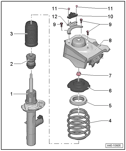
1 - Shock Absorber
- On vehicles with electronically controlled damping, perform the function "Adapt the control position" with the Vehicle Diagnostic Tester.
- If the control position was reprogrammed and if the vehicle has lane assist, then it will then be necessary to calibrate the driver assistance systems front camera.
- On vehicles with level control system sensor, perform headlamp basic setting.
2 - Stop Buffer
3 - Protective Sleeve
4 - Coil Spring
- Surface of spring coil may not be damaged.
- Removing and installing.
5 - Axial Groove Ball Bearing
6 - Suspension Strut Bearing
- Note the installed position. Refer to
7 - Nut
- 60 Nm
- Always replace if removed
8 - Suspension Strut Dome
9 - Bolt
- 15 Nm + 90º
- Always replace if removed
10 - Left Front Body Acceleration Sensor -G341- or Right Front Body Acceleration Sensor -G342-
- Note the installed position. Refer to
- Removing and installing. Refer to → Chapter "Left/Right Front Body Acceleration Sensor -G341-/-G342-, Removing and Installing".
11 - Bolt
- 5 Nm
- Always replace if removed
12 - Bracket
- Installed on a vehicle with electronic damping
- Observe the installation position between the right and left.
Suspension Strut, Removing and Installing
Special tools and workshop equipment required
- Spreader Tool -3424-
- Torque Wrench 1331 5-50Nm -VAG1331-
- Torque Wrench 1332 40-200Nm -VAG1332-
- Engine and Gearbox Jack -VAS6931-
- Engine/Gearbox Jack Adapter - Wheel Hub Support -T10149-
Removing
- Remove the plenum chamber cover. Refer to → Body Exterior; Rep. Gr.50; Bulkhead; Plenum Chamber Cover, Removing and Installing.
- Loosen drive axle bolt on the wheel hub. Refer to → Chapter "Drive Axle Threaded Connection, Loosening and Tightening".
- Remove the front wheel. Refer to → Chapter "Wheels and Tires".
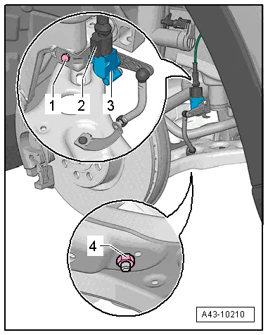
- Disconnect the vehicle Left Front Level Control System Sensor -G78- or Right Front Level Control Sensor -G289- coupling rod from the control arm by removing the nut -4-.
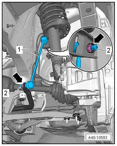
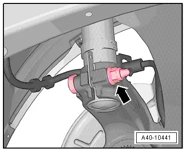
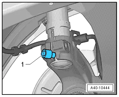
- Remove the nut -upper arrow- from the coupling rod -1- by counterholding with a multipoint socket on the threaded pin -2- if necessary.
- Remove the nut -right arrow- of the coupling rod -1- on the suspension strut by counterholding with a multipoint socket on the threaded pin -2- if necessary.
 Note
Note
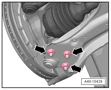
Ignore -left arrow-.
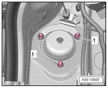
- Remove the nuts -arrows-.
- Remove both the wheel bearing housing and ball joint from the control arm.
 Note
Note
Pay attention during the assembly work that the ball joint rubber boot is not damaged. If necessary protect the ball joint rubber boot against damage.
- Remove the drive axle outer joint from the wheel hub.
- Secure drive axle to body using wire.
 Note
Note
The drive axle must not hang down, otherwise the inner joint will be damaged by overflexing.
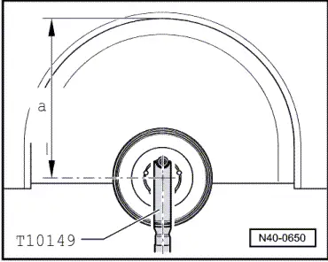
- Bolt ball joint to control arm again.
- Secure the Engine and Gearbox Jack -VAS6931- using the Engine/Gearbox Jack Adapter - Wheel Hub Support -T10149- to the wheel hub with a wheel bolt.
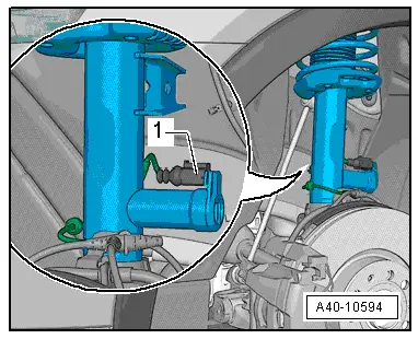
- On vehicles with electronic damping, disconnect the connector -1- and free up the wire from the suspension strut.
- Disconnect threaded connection of wheel bearing housing/suspension strut -arrow-.
- Insert the Spreader Tool -3424--1- into wheel bearing housing slot.
- Turn the ratchet 90º and remove it from the Spreader Tool -3424-.
- Press the brake rotor toward the suspension strut by hand, otherwise shock absorber tube may become tilted in the hole of wheel bearing housing.
- Pull off wheel bearing housing downward from the shock absorber tube and lower using the Engine and Gearbox Jack -VAS6931- until the shock absorber tube hangs freely.
- Tie up the wheel bearing housing with a wire on the bracket/subframe.
- Remove the Engine and Gearbox Jack -VAS6931- from under the wheel bearing housing.
- Remove the bolts -1- for upper strut mount and remove suspension strut.
The illustration shows a vehicle with electronic damping.
Installing
Installation is reverse of removal, noting the following:
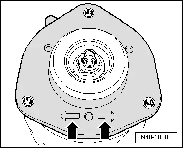
One of the two markings -arrows- on the spring plate must point in the direction of travel.
Applies to a vehicle with electronically controlled damping:
Left suspension strut installation position:
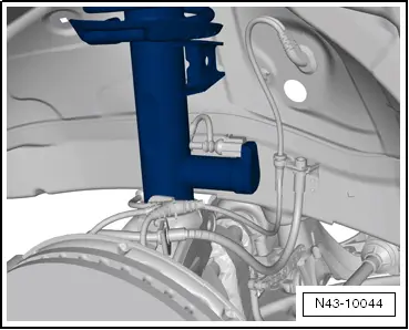
The suspension strut must be installed so that the Left Front Damping Adjustment Valve -N336- faces opposite the drive direction.
Right suspension strut installation position:
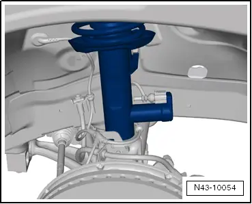
The suspension strut must be installed so that the Right Front Dampening Adjustment Valve -N337- faces opposite the drive direction.
Continuation for both sides:
- Check the installation position of the Left Front Body Acceleration Sensor -G341- and Right Front Body Acceleration Sensor -G342- bracket.
 Note
Note
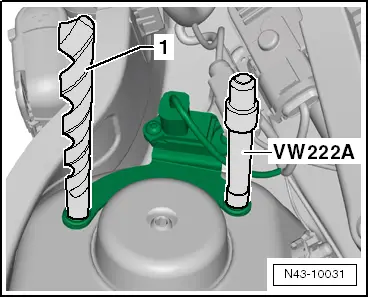
- Use an 11 mm drill bit -1- and the Pilot Drift -VW222A- to check the installation position.
- The holes in the retainer must align with the holes in the shock absorber dome.
- Install the plenum chamber cover. Refer to → Body Exterior; Rep. Gr.50; Bulkhead; Plenum Chamber Cover, Removing and Installing.
- Install the front wheel. Refer to → Chapter "Wheels and Tires".
- An axle alignment may be required. Refer to → Chapter "Evaluating Need for Axle Alignment".
- On vehicles with electronically controlled damping, perform the function "Adapt the control position" with the Vehicle Diagnostic Tester.
- If the control position was reprogrammed and if the vehicle has lane assist, then it will then be necessary to calibrate the driver assistance systems front camera. Refer to → Chapter "Driver Assistance Systems Front Camera, Calibrating".
- On vehicles with level control system sensor, perform headlamp basic setting. Refer to → Electrical Equipment; Rep. Gr.94; Headlamp, Adjusting.
Suspension Strut, Servicing
Special tools and workshop equipment required
- Torque Wrench 1332 40-200Nm -VAG1332-
- Spring Compressor Kit - Spring Tensioner -VAG1752/1-
- Spring Compressor Kit - Spring Retainer w/Inserts -VAG1752/4-
- Shock Absorber Set -T10001-
- Ratchet (Commercially Available)
Coil Spring, Removing
- Remove the suspension strut. Refer to → Chapter "Suspension Strut, Removing and Installing".
- Pretension the coil spring using the Spring Compressor Kit - Spring Tensioner -VAG1752/1- until the upper axial groove ball bearing is free.
- Remove hex nut from piston rod.
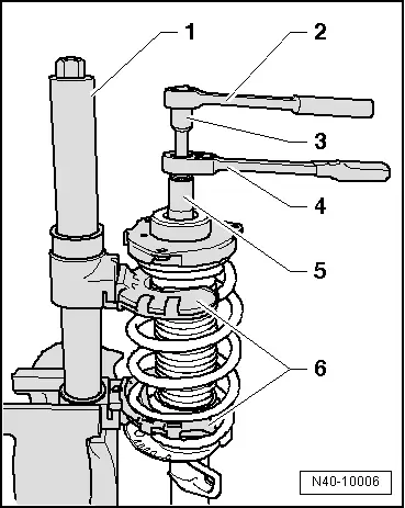
- Remove the individual components of the suspension strut and coil spring with the Spring Compressor Kit - Spring Tensioner -VAG1752/1-.
1 - Spring Compressor Kit - Spring Tensioner -VAG1752/1-
2 - Torque Wrench 1332 40-200Nm -VAG1332-
3 - Shock Absorber Set - Extension SW7 -T10001/8-
4 - Shock Absorber Set - Reversible Ratchet -T10001/11-
5 - Shock Absorber Set - Socket -T10001/5-
6 - Spring Compressor Kit - Spring Retainer w/Inserts -VAG1752/4-
 WARNING
First pre-load spring far enough so that tension is relieved on upper spring plate!
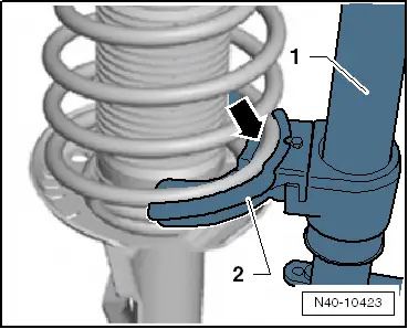
- Make sure the coil spring fits correctly inside the Spring Compressor Kit - Spring Retainer with Inserts -VAG1752/4--arrow-.
Coil Spring, Installing
- Place coil spring with Spring Compressor Kit - Spring Tensioner -VAG1752/1- on lower spring support.
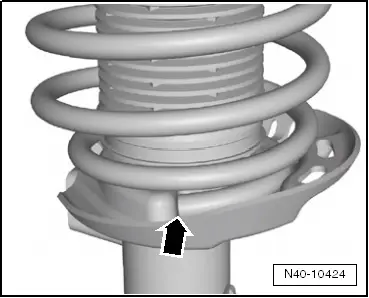
End of spring coil must rest against stop -arrow-.
- Tighten the new nut on piston rod. Refer to → Chapter "Overview - Suspension Strut and Upper Control Arm".
- Relieve the tension on the Spring Compressor Kit - Spring Tensioner -VAG1752/1- and remove from the coil spring.
- Install the suspension strut. Refer to → Chapter "Suspension Strut, Removing and Installing".
READ NEXT:
 Overview - Lower Control Arm and Ball Joint
1 - Control Arm
Control arm with mounting bracket, removing and installing. Refer to
→ Chapter "Lower Control Arm, Removing and Installing".
2 - Bonded Rubber Bush
Lower Control Arm, Removing and Installing
Special tools and workshop equipment
required
Locating Pins -T10096-
Torque Wrench 1332 40-200Nm -VAG1332-
Removing
- Before starting work, determine the measurement
-a-, for example
Ball Joint, Removing and Installing
Special tools and workshop equipment
required
Puller - Ball Joint -3287A-
Digital Torque Wrench -VAG1756A-
Torque Wrench 1332 Insert - Ring Wrench - 18mm -VAG1332/10-
Removing
- Loo
SEE MORE:
Cover and Cushion, Removing and Installing
Cover and Cushion, Removing and Installing, Bench Seat
Removing
- Remove the rear bench seat. Refer to
→ Chapter "Bench Seat/Single Seat, Removing and Installing".
- Pry up the seat cover clamping strip
-2- with a screwdriver along the seat frame from the
molded part.
-&nb
Rear Brake Pads, Removing and Installing
Brake Pads, Removing and Installing, Brakes 1KU
If old brake pads are being replaced with new ones, then it
is necessary to check the brake rotor thickness for wear. Pay
attention to the wear specifications for the brake rotor, refer
to
→ Chapter "Brakes Technical Data".
Special too
