Audi Q3: Vehicle Alignment
Axle Alignment Information
Wheel alignment must only performed using VW/Audi-approved wheel alignment equipment.
Each time wheels are aligned, both front and rear wheels must be aligned.
Otherwise, proper vehicle drivability cannot be ensured.
Otherwise centering of toothed shaft cannot be guaranteed!
 Note
Note
- Do not carry out axle alignment until the vehicle has been driven 1000 to 2000 km in order to allow the coil springs to settle.
- The individual specifications should be followed as exactly as possible when making adjustments.
- Vehicle instability can also be caused by the wheels having a residual imbalance and/or radial run-out which is too great.
Vehicles pulling to one side and vehicles involved in an accident
The cause for this could be that steering rack in steering gear does not stand exactly in the center when steering straight ahead.
The steering support may pull slightly to the left or to the right. The result is a vehicle which pulls to the side.
If a vehicle is aligned due to a complaint "vehicle pulls to one side or pulls askew", center position of steering rack must always be checked.
 WARNING
If the vehicle has ESP or ABS, calibrate the Steering Angle Sensor -G85- after making any adjustments on the suspension using the Vehicle Diagnosis Tester.
 WARNING
If vehicle will be driving on the streets, all screws and nuts must be tightened properly!
 WARNING
There is a risk of injury if the engine starts automatically in vehicles with the Start/Stop System.
- For vehicles with an activated Start/Stop System (recognizable from a notification in the instrument cluster), the motor can be started automatically if needed.
- Make sure that the start/stop system is deactivated when working on the vehicle (turn off the ignition, turn on the ignition when necessary).
Test Prerequisites
- Check suspension, steering and steering linkage for excessive play and damage, repair if necessary.
- Tread depth difference may be no more than 2 mm on an axle.
- Tires inflated to prescribed pressure
- Drive the vehicle onto the alignment rack without tension. Move the vehicle back and forth if necessary to relieve any tension on the axle components.
- Vehicle accurately aligned, suspension bounced and rocked several times
- Make sure that the sliding plates and turn tables are not touching the end stop when checking the wheel alignment.
- The steering wheel must be "evened out" into the center position before beginning the measuring and adjusting. Use Steering Wheel Scales -VAS6458- for this.
- Vehicle is in curb weight position.
1) Curb weight means: the weight of the vehicle ready for the road (completely filled fuel tank and windshield washer fluid reservoir, spare tire, vehicle tool kit, vehicle jack)
- Perform wheel run-out compensation: permissible axial run-out of the wheel rims can exceed the specified toe setting tolerance. If compensation for wheel run-out is not performed, it will not be possible to obtain a correct toe-in adjustment.
- The measurement sensor must be properly adjusted and attached to the vehicle; observe device manufacturer's operating instructions.
- If necessary, contact the manufacturer for familiarization with the proper use of the equipment.
- Vehicle alignment platforms and the alignment equipment/alignment computers can deviate from their original calibration over time therefore they should be calibrated at least once a year during maintenance.
- Handle highly sensitive units with care.
Measurement Preparations
Measurement Preparations
Special tools and workshop equipment required
- Brake Pedal Actuator -VAG1869/2-.
- Steering Wheel Scales -VAS6458-
- Wheel Alignment Computer released by VW/Audi
- The measurement sensor must be properly adjusted and attached to the vehicle; observe device manufacturer's operating instructions.
- Make sure that the sliding plates and turn tables are not touching the end stop when checking the wheel alignment.
- Drive the vehicle onto the alignment rack without tension. Move the vehicle back and forth if necessary to relieve any tension on the axle components.
- The steering wheel must be "evened out" into the center position before beginning the measuring and adjusting. Use Steering Wheel Scales -VAS6458- for this.
Preparation Work for Calibrating and Adjusting Driver Assist Systems
Perform the following steps using "quick access" if one or more systems on the vehicle will be calibrated/adjusted (without a previous axle alignment):
- Before driving the vehicle onto the alignment stand, make sure there is enough space between the vehicle and the ACC Adjustment Device. Distance between the setting device and the vehicle: 120 cm +- 2.5 cm.
- If there is not sufficient space, drive vehicle backward on alignment stand in order to be able to use the corresponding space.
- Check the DTC memory and correct any malfunctions before beginning the calibration/adjusting.
- Vehicle accurately aligned, suspension bounced and rocked several times
- Make sure that the sliding plates and turn tables are not touching the end stop when checking the wheel alignment.
- Connect the battery charger. Refer to → Electrical Equipment; Rep. Gr.27; Battery; Battery, Charging.
- Position the front wheels so they are straight.
- Connect the Vehicle Diagnosis Tester to the vehicle and guide the diagnostic cable through the open window.
- The vehicle exterior lamps are off.
- All the vehicle doors are closed.
- Using the screen, turn on the calibration/adjustment on the wheel alignment computer.
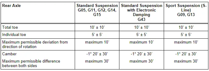
Axle Alignment Specified Values
Specifications valid for all engine versions
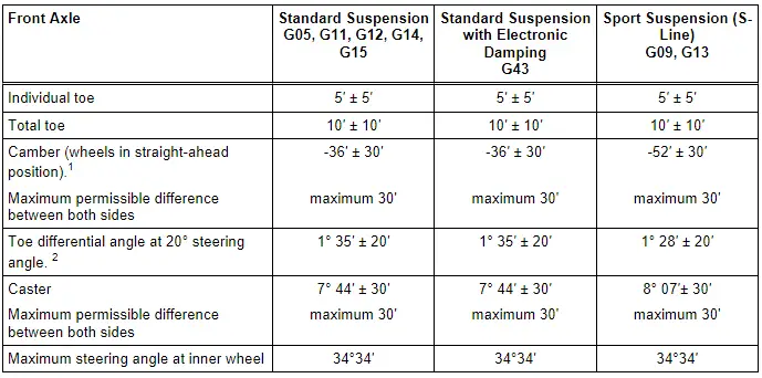
1) Camber corrections are not possible. It can only be slightly corrected by pushing the subframe.
2) Wheel stop on outer wheel is reduced by this amount. It can also be indicated negatively in alignment computer, depending on manufacturer.
Axle Alignment Procedure
Special tools and workshop equipment required
- Steering Wheel Scales -VAS6458-
Work procedure for axle alignment, overview
 Note
Note
Vehicle must only be measured at curb weight.
Observe the following work sequence!
1 - Drive the vehicle onto the alignment rack without tension. Move the vehicle back and forth if necessary to relieve any tension on the axle components.
2 - The steering wheel must be "evened out" into the center position before beginning the measuring and adjusting. Use Steering Wheel Scales -VAS6458- for this.
3 - Perform wheel run-out compensation. Refer to → Chapter "Wheel Run-Out Compensation".
4 - Check the maximum steering angle. Refer to → Chapter "Maximum Steering Angle, Checking".
5 - Check front axle camber and adjust if necessary. Refer to → Chapter "Front Axle Camber, Adjusting".
6 - Check rear axle camber and adjust if necessary. Refer to → Chapter "Rear Axle Camber, Adjusting".
7 - Check rear axle toe and adjust if necessary. Refer to → Chapter "Rear Axle Toe, Adjusting".
8 - Check the front axle toe angle and adjust if necessary. Refer to → Chapter "Front Axle Toe, Adjusting".
 Note
Note
- If adjustments were made to the suspension during the axle alignment on vehicles with ESP or ABS, a calibration of the Steering Angle Sensor -G85- must be performed using the Vehicle Diagnosis Tester.
- If the rear axle setting was changed, the lane assist must be calibrated on vehicles with lane assist. Refer to → Chapter "Driver Assistance Systems Front Camera, Calibrating", and on vehicles with a rearview camera system, the rearview camera system must be calibrated. Refer to → Communication; Rep. Gr.91; Rearview Camera System; Rearview Camera System, Calibrating.
Evaluating Need for Axle Alignment
- Vehicle shows handling problems.
- Involved in an accident.
- Axle components were removed.
- Tire wear patterns are uneven.
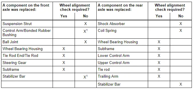
1: If the subframe was not secured with Locating Pins -T10096-, an axle alignment is required.
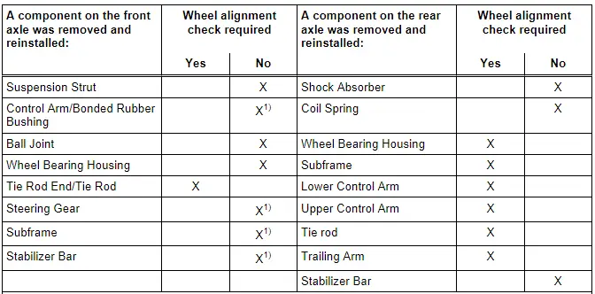
1) If the subframe was not secured with Locating Pins -T10096-, an axle alignment is required.
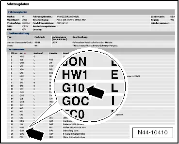
Explanations of Production Control Numbers (PR Number)
The vehicle data plate documents which front/rear axle or tire pressure monitoring system is installed using the corresponding PR numbers.
There is a vehicle data label in the spare wheel well and also one in the customer Maintenance booklet.
Information regarding each chassis installed can be found in ELSA in Parts Catalog under "Vehicle Data".
In this example, the sport suspension G10 is installed in the vehicle (see the magnified area of the illustration)
G05, G11, G12, G14, G15 = Standard suspension
G43 = standard suspension with electronic damping
G09, G15 = Sport suspension (S-line)
Front Axle Camber, Adjusting
Special tools and workshop equipment required
- Torque Wrench 1332 40-200Nm -VAG1332-
Procedure
Camber cannot be adjusted.
The camber can only be centered evenly within the tolerance range by sliding the subframe.
- It is only permissible to slide the subframe to the left or right. Under no circumstances slide it in or against the direction of travel!
- Remove the noise insulation. Refer to → Body Exterior; Rep. Gr.66; Noise Insulation; Noise Insulation, Removing and Installing.
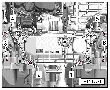
- Remove the bolts -1 through 6- one after the other and install new bolts loosely.
- Move the subframe sideways until the camber is even on both sides.
- Tighten the subframe bolts -1 through 6-.
After sliding subframe and steering gear along with it as well, clearance between universal joint of steering column and cutout of plenum chamber bulkhead must be checked.
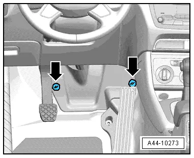
- Remove securing nuts -arrows- and remove foot well trim.
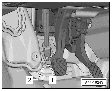
There must be at least 5 mm of free space all around between the universal joint -1- and the cutout of the plenum chamber bulkhead -2-.
Rear Axle Camber, Adjusting
Special tools and workshop equipment required
- Torque Wrench 1332 40-200Nm -VAG1332-
- 18 mm socket from the Shock Absorber Set -T10001-
- Insert Tool - 18mm -T10179-
Procedure
 Note
Note
In the following procedure, a vehicle with FWD is shown.
- Remove the nut -A- on the upper control arm threaded connection from the subframe and loosely install a new nut.
- To turn the eccentric bolt -B-, turn the hex head at the "top of the bolt".
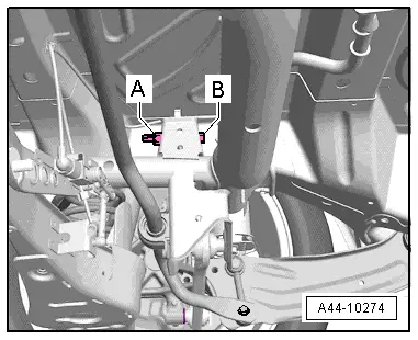
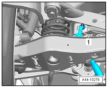
- Set the camber by turning the eccentric screw -B- using the 18 mm socket -item 1-.
 Note
Note
The maximum adjustment range is 90º to left or right of center position.
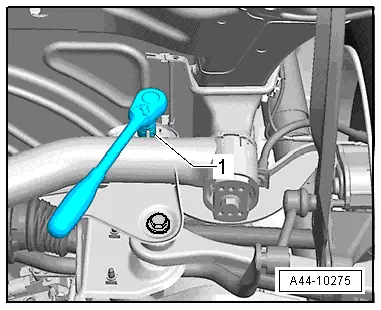
- Tighten the nut -A- using the Insert Tool - 18mm -T10179-.

- Use the Insert Tool - 18mm -T10179--item 1- as shown.
- After the nut -A- is tightened, check the camber value once more. Refer to → Chapter "Axle Alignment Specified Values".
Rear Axle Toe, Adjusting
Special tools and workshop equipment required
- Torque Wrench 1332 40-200Nm -VAG1332-
Procedure
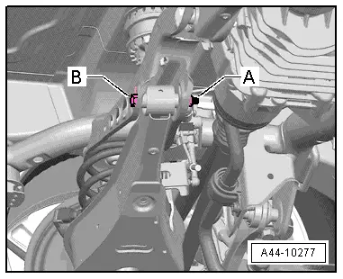
- Remove the nut -A- on the lower control arm threaded connection from the subframe and loosely install a new nut.
- Adjust toe by turning eccentric screw -B-.
 Note
Note
The maximum adjustment range is 90º to left or right of center position.
- Tighten the nut -A-.
- After the nut -A- is tightened, check the toe value once more. Refer to → Chapter "Axle Alignment Specified Values".
Front Axle Toe, Adjusting
Procedure
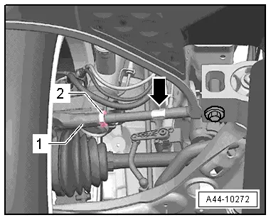
- To loosen or tighten the lock nut -2-, counterhold at the tie rod end -1- with a suitable tool.
- Loosen the lock nut -2-.
- Adjust toe on left and right-hand wheels at hex -arrow-.
 Note
Note
- Make sure that boot on steering gear is not damaged or twisted. Twisted boots wear out quickly.
- Only tighten the lock nuts when the vehicle is resting on the ground - the tie rod end must be parallel to the suspension strut steering lever.
- Tighten the lock nut -2- and check the toe-in value again.
After tightening the lock nut -2-, it is possible that the value deviates slightly.
If the measured toe nevertheless lies within the tolerance, the adjustment is correct. Refer to → Chapter "Axle Alignment Specified Values".
Wheel Run-Out Compensation
A correct toe-in adjustment will not be possible without performing lateral run-out compensation!
The lateral run-out of the wheel must be compensated for. Otherwise, measurement will result in false readings.
Permissible axial run-out of the wheel rims can exceed the specified toe setting tolerance. If compensation for wheel run-out is not performed, it will not be possible to obtain a correct toe-in adjustment.
Follow the operating instructions provided by the manufacturer of the alignment equipment.
Maximum Steering Angle, Checking
The wheel alignment computer determines the maximum steering angle.
- If the maximum steering angle has been determined on the alignment equipment, so that the value is not within the tolerance, then check for damage or deformations to the steering and suspension components and inspect the symmetry of the ties rod. In this case, shorten the "longer" tie rod end (install it deeper into the tie rod) and replace any damaged components.
- If a steering wheel fault is determined on the alignment equipment when setting the center position of the steering, then check the steering and suspension for damage or deformations and replace any damaged components. Check the tie rod symmetry as well.
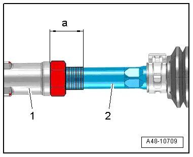
- Measure the dimension -a- on the "shorter" tie rod head. Shorten the "longer" tie rod head to the same dimension. To do this, install the tie rod head -1- deeper on the tie rod -2-.
Dimension -a- of right tie rod end should equal the dimension -a- of left tie rod end; maximum permissible difference between right and left is less than 2.5 mm.
- When the steering wheel returns to the center position, let the steering wheel "come to the center" using even movements.
READ NEXT:
 Driver Assistance Systems Front Camera
Driver Assistance Systems Front Camera, Calibrating
Special tools and workshop equipment
required
Setting Device Basic Set -VAS6430/1-
Wheel Alignment Computer
Vehicle Diagnostic Tester
Steering Wheel
Overview - Steering Wheel
1 - Steering Column Electronics Control Module -J527-
With Airbag Spiral Spring/Return Spring with Slip Ring -F138-
Removing and installing. Refer to
→SEE MORE:
Jump starting
Preparation
You should only perform the steps that follow if
you have the necessary tools and technical expertise.
If the engine does not start because the vehicle
battery is drained, you can jump start your vehicle
using another vehicle. Jump start cables are
needed to do this.
Both vehicle batteri
Door, Adjusting
Special tools and workshop equipment
required
Gauge - Gap Adjustment -3371-
Door Adjustment Template -T40038 /16-
Check the Height Adjustment using the Door Adjustment
Template -T40038 /16-.
- The template must lay on the top of the trim strip
-1- as shown.
- The height is 