Audi Q3: Driver Assistance Systems Front Camera
Driver Assistance Systems Front Camera, Calibrating
Special tools and workshop equipment required
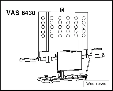
- Setting Device Basic Set -VAS6430/1-
- Wheel Alignment Computer
- Vehicle Diagnostic Tester
Calibration is necessary if:
 Note
Note
Before calibrating the Driver Assistance Systems Front Camera -R242-, check the DTC memory and correct any faults. To calibrate the Driver Assistance Systems Front Camera -R242-, the vehicle driving direction must be specified and serves as the reference position for the tool Setting Device Basic Set -VAS6430-. The Driver Assistance Systems Front Camera -R242- may only be calibrated using alignment equipment approved by VW/Audi. Only use the Setting Device Basic Set -VAS6430- to calibrate the lane assist.
- "No or incorrect basic setting/adaptation" is stored actively in the DTC memory.
- the Driver Assistance Systems Front Camera -R242- was removed and installed or replaced,
- The windshield is replaced or removed,
- the rear axle toe was adjusted,
- the vehicle suspension was changed, for example, changing from standard to sport suspension,
- for vehicles with electronic damping, the Left Front Level Control System Sensor -G78- and Right Front Level Control Sensor -G289- were reprogrammed.
 Note
Note
- Check if the Driver Assistance Systems Front Camera -R242- is seated correctly in the bracket.
- Perform a visual inspection to see if the camera visual area is free.
- Check the DTC memory and correct any malfunctions before beginning the calibration.
There are two choices for calibrating:
The "quick access"
This procedure should be selected for the following activities if only the calibration will be performed.
- "No or incorrect basic setting/adaptation" is stored actively in the DTC memory.
- the Driver Assistance Systems Front Camera -R242- was removed and installed or replaced,
- The windshield is replaced or removed,
- The control position on vehicles with air suspension was reprogrammed.
The "complete alignment"
This procedure should be selected for the following activities if a calibration and a suspension adjustment will be performed.
- The rear axle toe was adjusted.
- the vehicle suspension was changed, for example, changing from standard to sport suspension.
 Note
Note
Both procedures are programmed into the axle alignment computer. The respective procedure is performed automatically. It is only necessary to select the appropriate program for the procedure that will be performed.
Preparation Work for Calibrating and Adjusting Driver Assist Systems. Refer to → Chapter "Preparation Work for Calibrating and Adjusting Driver Assist Systems".
Calibration/adjusting without a previous axle alignment
- Select the lane assist calibration procedure in the alignment computer.
- Install the quick clamps on all four wheels.
- Mount the measurement sensor to the rear wheels.
- Perform a wheel run-out compensation and the rear wheels.
Calibrating/adjusting with a previous axle alignment
- Connect the battery charger. Refer to → Electrical Equipment; Rep. Gr.27; Battery; Battery, Charging.
- Position the front wheels so they are straight.
- Connect the Vehicle Diagnostic Tester to the vehicle and guide the diagnostic cable through the open window.
- Turn off all vehicle exterior lamps.
- Close all vehicle door.
Calibration/adjusting procedure with or without a previous axle alignment
- Select calibration/adjusting on the wheel alignment computer.
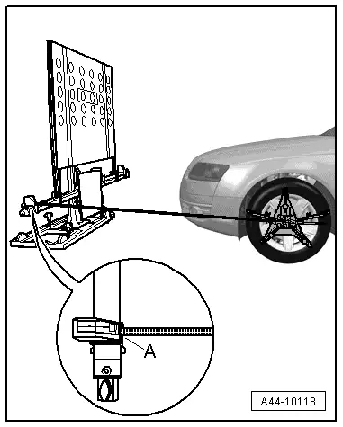
- Position the Setting Device Basic Set -VAS6430/1- at a distance of -A- 150 cm +- 2.5 cm from the center of the wheel hub on the front wheels to the beam on the Setting Device Basic Set -VAS6430/1- as shown in the illustration.
 Note
Note
The Setting Device Basic Set -VAS6430/1- must not be moved on the calibration beam.
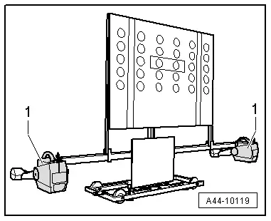
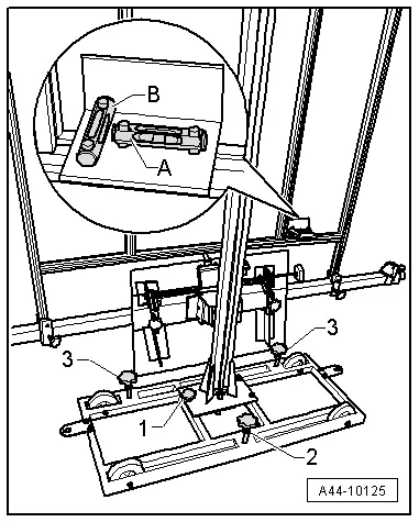
- Mount the front wheel measuring sensors -1- to the Setting Device Basic Set -VAS6430/1-.
 Note
Note
The alignment stand must be in the lowest level position for the next step.
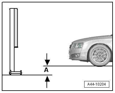
- Enter the height value -A- between the Setting Device Basic Set -VAS6430/1- contact patch and the wheel contact surface as shown in the illustration and enter it in the alignment computer.
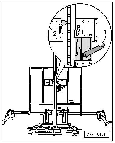
- Loosen the bolt -arrow- and place the measuring bar -1- on the floor.
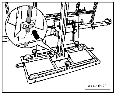
- Adjust the calibration panel to the specified height -2- according to the alignment computer using the crank -1-.
If the specified height was reached -2-, then the measuring bar must be pushed slightly upward and secured with the clamping screw.
 Note
Note
If in later procedure the height of the calibration board must be corrected, make sure the measuring bar is touching the ground when this is being done.
- Level the bubble level -A- using the adjusting screw -1-.
The bubble adjustment -A- serves to compare the ground conditions.

- Move the Setting Device Basic Set -VAS6430/1- sideways -arrow B- until the display on the alignment computer is within the tolerance range.
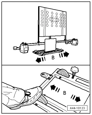
- Secure the Setting Device Basic Set -VAS6430/1- by tightening the bolts -2- and -3- slightly. (This prevents the Setting Device Basic Set -VAS6430- from rolling away).
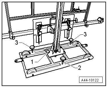
- Turn the precision adjustment screw -1- until the display on the wheel alignment computer is located within the tolerance range.
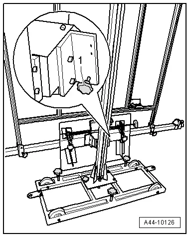
- Level the bubble level -A- using the adjusting screw -1-.
- Level the bubble level -B- using the adjusting screw -2-.
And further work is performed using the Vehicle Diagnosis Tester in Guided Fault Finding.
- Turn on the ignition.
- Touch Guided Fault Finding.
- Select in succession:
- Brand
- Type
- Model year
- Version
- Engine Code
- Confirm data entered.
Wait until the Vehicle Diagnosis Tester has checked all control modules in vehicle.
- Press the go to button and select "function/component selection".
- Select the corresponding program in "Guided Functions".
Now follow the instructions on the screen to perform the calibration.
 Note
Note
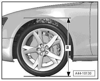
A step is performed in guided fault finding next to determine the body height.

- Determine the body height -a- at all four wheels in the center of the wheel between the wheel contact surface and the lower edge of the fender.
Special Tools
Special tools and workshop equipment required
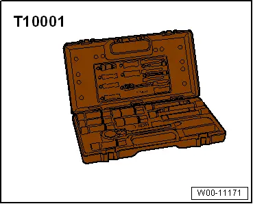
- Shock Absorber Set -T10001-
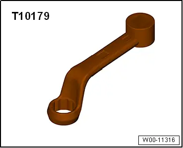
- Insert Tool - 18mm -T10179-
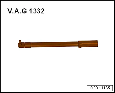
- Torque Wrench 1332 40-200Nm -VAG1332-
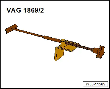
- Brake Pedal Actuator -VAG1869/2-.
- Setting Device Basic Set -VAS6430/1-
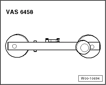
- Steering Wheel Scales -VAS6458-
READ NEXT:
 Steering Wheel
Overview - Steering Wheel
1 - Steering Column Electronics Control Module -J527-
With Airbag Spiral Spring/Return Spring with Slip Ring -F138-
Removing and installing. Refer to
→
Steering Column
Overview - Steering Column
Note
Always replace corroded bolts/nuts.
1 - Instrument Panel Central Tube
2 - Shear Bolt
Tighten the shear bolt until head shears off
SEE MORE:
CV Joint, Servicing, Drive Axle with Triple Roller Joint AAR3300i, Mounted
in Transmission
Special tools and workshop equipment
required
Tripod Joint Tool -T10065-
Puller - Driveshaft -T10382-
Hose Clip Pliers -VAG1275A-
Torque Wrench 1331 5-50Nm -VAG1331-
Torque Wrench 1332 40-200Nm -VAG1332-
Clamping Pliers -VAG1682A-
Press Plate -VW401-
Press Plate -VW402-
Press P
Overview - Antenna Systems
The antenna system consists of the Roof Antenna -R216- and
the window antenna.
Roof Antenna -R216-
GPS Antenna -R50-, only on 7T2, 7T6 and 7Q4
Telephone Antenna -R65-, only on 9ZF and 9ZW
Satellite Antenna -R170-, only North America and QV8
Auxiliary Heater Antenna -R182-, only Europe a
