Audi Q3: Wheel Bearing Unit, Removing and Installing
Special tools and workshop equipment required
- Torque Wrench 1332 40-200Nm -VAG1332-
Removing
- Loosen the drive axle threaded connection on the wheel side. Refer to → Chapter "Drive Axle Threaded Connection, Loosening and Tightening".
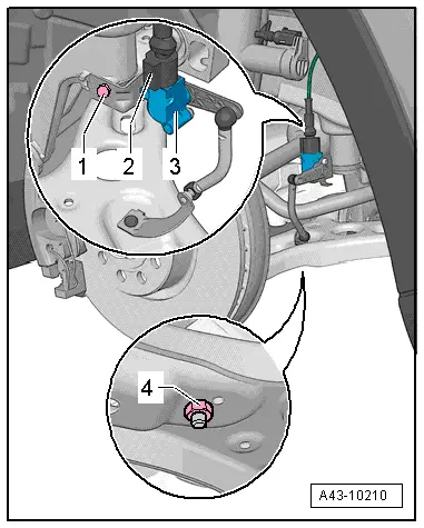
- If installed, remove the nut -4- and free up the coupling rod from the Left Front Level Control System Sensor -G78--3-.
- Remove the ABS speed sensor. Refer to → Brake System; Rep. Gr.45; Sensors; Right/Left Front ABS Wheel Speed Sensor G45/G47, Removing and Installing.
- Remove the brake rotor. Refer to → Brake System; Rep. Gr.46; Front Brakes; Brake Rotor, Removing and Installing.
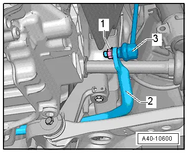
- Remove the nut -1-, remove the coupling rod -3- from the stabilizer bar -2- and pivot aside.
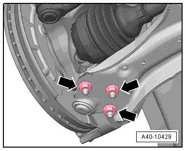
- Remove the nuts -arrows-.
- Remove the control arm from the ball joint.
- Remove the drive axle outer joint from the wheel hub.
- Secure drive axle to body using wire.
- Reconnect the ball joint in the control arm.
- Install the nuts -arrows-.
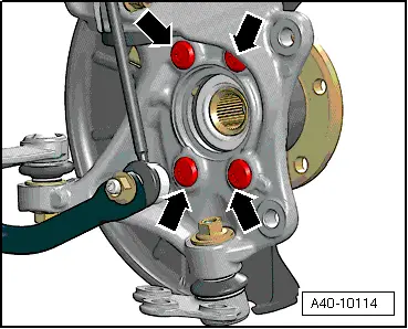
- Remove the bolts -arrows-.
- Remove wheel bearing unit from wheel bearing housing.
 Caution
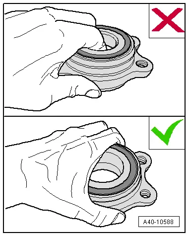
Avoid contaminating with dirt and damaging the seal when lifting, setting down/storing.
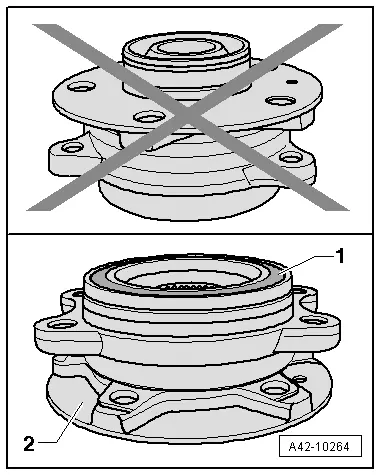
- The wheel bearing -1- must face up in order to remove the wheel bearing unit.
- Always set the wheel bearing unit down on the wheel hub -2-.
- Never reach into the inside when lifting the wheel bearing.
- Hold the wheel bearing only on the outside.
Installing
Install in reverse order of removal while noting the following:
- Install the brake caliper. Refer to → Brake System; Rep. Gr.46; Front Brakes; Brake Caliper, Removing and Installing.
Tightening Specifications
- Brake rotor.
READ NEXT:
 Overview - Drive Axle
Overview - Drive Axle, Drive Axle with CV Joint VL107
1 - Bolt
200 Nm +180º
Always replace if removed
Loosening and tightening the twelve-point bolt
→ Chapter "Drive Axl
Drive Axle, Removing and Installing, Drive Axle with Bolted CV Joint VL
107
Removing
- Loosen the drive axle threaded connection on the wheel side.
Refer to
→ Chapter "Drive Axle Threaded Connection, Loosening and
Tightening".
- Remove the front wheel
Drive Axle, Removing and Installing, Drive Axle with Triple Roller Joint
AAR3300i, Mounted on Transmission Stub Shaft
Special tools and workshop equipment
required
Slide Hammer Set -VW771-
Tensioning Strap -T10038-
Puller - Driveshaft -T10382-
Torque Wrench 1332 40-200Nm -VAG1332-
Digital Torque Wrench
SEE MORE:
Adjusting side assist
Applies to: vehicles with side assist
You can adjust the side assist to your preferences.
The settings depend on the vehicle equipment.
Applies to: MMI: Select on the home screen:
VEHICLE > Driver assistance > Side assist.
Possible settings:
The system can be switched on and off. If the s
Turn signal and high beam lever
Fig. 38 Operating lever: switching the light functions on
and off
The lever operates the turn signals, the high
beams and the headlight flasher.
Turn signals
The turn signal will activate when you move the
lever into a turn signal position while the ignition
is switched on. The respective or
ind
