Audi Q3: Overview - Drive Axle
Overview - Drive Axle, Drive Axle with CV Joint VL107
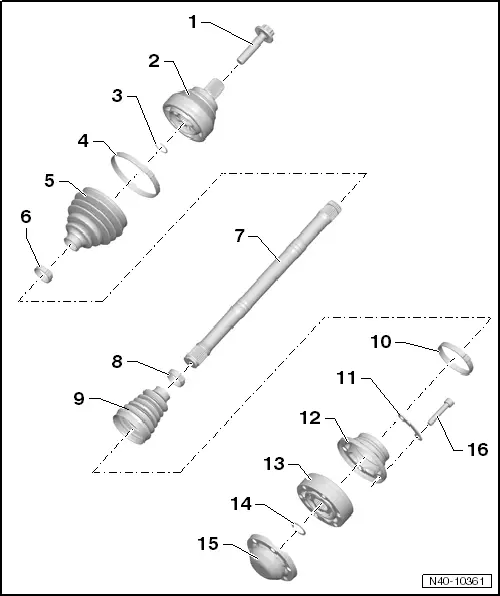
1 - Bolt
- 200 Nm +180º
- Always replace if removed
- Loosening and tightening the twelve-point bolt → Chapter "Drive Axle Threaded Connection, Loosening and Tightening"
- Before installing, clean the threads in the CV joint with a tap.
2 - Outer CV Joint
- When installing the joint on the profile shaft, the splines on the profile shaft must be lightly coated with grease used in joint.
- Checking. Refer to → Chapter "Outer CV Joint, Checking".
- Removing. Refer to → Fig. "Removing the Outer CV Joint".
- Installing.
3 - Locking Ring
- Always replace if removed
- Insert in shaft groove
4 - Clamp
- Always replace if removed
- Tensioning.
5 - CV boot for outer CV joint
- Check for tears and scuffing
6 - Clamp
- Always replace if removed
- Tensioning.
7 - Profile Shaft
8 - Clamp
- Always replace if removed
- Tensioning.
9 - CV Boot for Inner CV Joint
- Check for tears and scuffing
10 - Clamp
- Always replace if removed
- Tensioning.
11 - Locking Plate
12 - Cover
- Always replace if removed
- Drive off CV joint using drift
- Adhesive surface must be free of oil and grease
- Apply sealant between the joint and cover. Refer to → Fig. "Coat the sealing surface on the cover with sealant and then install it.".
13 - Inner CV Joint
- Replace only as complete unit.
- When installing the joint on the profile shaft, the splines on the profile shaft must be lightly coated with grease used in joint.
- Checking. Refer to → Chapter "Inner CV Joint, Checking".
- Removing.
- Installing.
14 - Locking Ring
- Always replace if removed
- Remove and install using Circlip Pliers -VW161A-. Refer to → Fig. "Circlip, Removing and Installing".
15 - Cover
- Always replace if removed
- Drive off CV joint using drift
- Apply sealant between the joint and cover. Refer to → Fig. "Coat the sealing surface on the cover with sealant and then install it.".
16 - Bolt
- Pre-tightening specification: diagonal sequence to 10 Nm.
- M8 tightening specification: diagonal sequence to 40 Nm.
- M10 tightening specification: diagonal sequence to 70 Nm.
- Always replace if removed
Overview - Drive Axle, Drive Axle with Triple Roller Joint AAR3300i, Mounted in Transmission
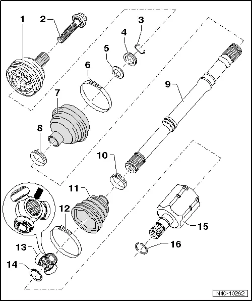
1 - Outer CV Joint
- Replace only as complete unit.
- Checking. Refer to → Chapter "Outer CV Joint, Checking".
- Removing.
- Installing: Drive onto shaft with plastic hammer until compressed circlip seats.
2 - Bolt
- 200 Nm +180º
- Always replace if removed
3 - Locking Ring
- Always replace if removed
- Insert in shaft groove
4 - Thrust Ring
- Not installed on all versions
- Installed position.
5 - Plate Spring
- Not installed on all versions
- Installed position.
6 - Clamp
- Always replace if removed
- Tensioning.
7 - CV Boot for CV Joint
- Check for tears and scuffing
- Material: polyelastomer
8 - Clamp
- Always replace if removed
- Tensioning.
9 - Drive Axle
10 - Clamp
- Always replace if removed
- Tensioning.
11 - CV Boot for Triple Roller Joint
- Check for tears and scuffing
12 - Clamp
- Always replace if removed
- Tensioning.
13 - Triple Roller Star with Rollers
The chamfer -arrow- points to drive axle splines.
14 - Locking Ring
- Always replace if removed
- Insert in shaft groove
15 - Joint
16 - Locking Ring
- Always replace if removed
Overview - Drive Axle, Drive Axle with Triple Roller Joint AAR3300i, Mounted on Transmission Stub Shaft
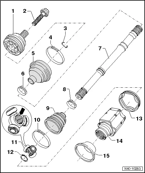
1 - Outer CV joint
- Replace only as complete unit.
- Checking. Refer to → Chapter "Outer CV Joint, Checking".
- Removing. .
- Installing: Drive onto shaft with plastic hammer until compressed circlip seats.
2 - Bolt
- 200 Nm +180º
- Always replace if removed
3 - Locking Ring
- Always replace if removed
- Insert in shaft groove
4 - Clamp
- Always replace if removed
- Tensioning.
5 - CV Boot for CV Joint
- Check for tears and scuffing
- Material: polyelastomer
6 - Clamp
- Always replace if removed
- Tensioning.
7 - Drive Axle
8 - Clamp
- Always replace if removed
- Tensioning.
9 - CV Boot for Triple Roller Joint
- Check for tears and scuffing
10 - Clamp
- Always replace if removed
- Tensioning.
11 - Triple Roller Star with Rollers
The chamfer -arrow- points to drive axle splines.
12 - Locking Ring
- Always replace if removed
- Insert in shaft groove
13 - Adapter
14 - Joint
15 - Cap
- Remove.
- Installing.
Overview - Drive Axle, Drive Axle with CV Joint, Inserted with Inner Splines
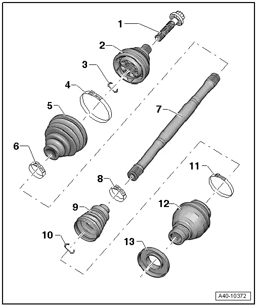
1 - Bolt
- 200 Nm +180º
- Always replace if removed
- Before installing, clean the threads in the CV joint with a tap.
2 - Outer CV Joint
- Replace only as complete unit.
- Divide the grease between the ball paths.
- Checking. Refer to → Chapter "Outer CV Joint, Checking".
- Removing. Refer to → Fig. "Removing Outer CV Joint".
- Installing: Using a plastic hammer, drive onto the shaft as far as the stop
3 - Locking Ring
- Always replace if removed
- Insert in shaft groove
4 - Clamp
- Always replace if removed
- Tensioning.
5 - CV Boot
- Check for tears and scuffing
- Material: polyelastomer
6 - Clamp
- Always replace if removed
- Tensioning.
7 - Drive Axle
8 - Clamp
- Always replace if removed
- Tensioning.
9 - CV Boot for CV Joint
- Check for tears and scuffing
- Material: polyelastomer
10 - Locking Ring
- Always replace if removed
- Insert in shaft groove
11 - Clamp
- Always replace if removed
- Tensioning.
12 - CV Joint
- Replace only as complete unit.
- Divide the grease between the ball paths.
- Removing. Refer to → Fig. "Removing Outer CV Joint".
- Installing: Using a plastic hammer, drive onto the shaft as far as the stop
13 - Protective Cap
- Remove.
- Installing.
Overview - Drive Axle, Drive Axle Heat Shield
FWD Vehicles:
- Tighten the nuts -arrows- to 35 Nm.
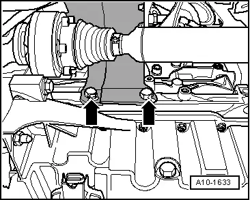
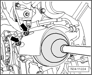
AWD vehicles version 1:
- Tighten the nuts -arrows- to 20 Nm.
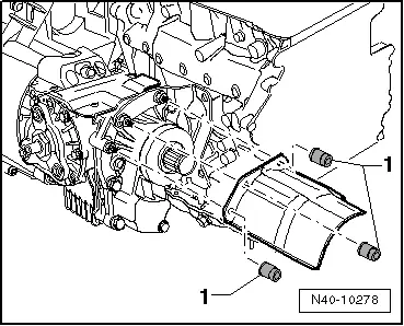
AWD vehicles version 2:
- Tighten the nuts -1- to 20 Nm.
READ NEXT:
 Drive Axle, Removing and Installing, Drive Axle with Bolted CV Joint VL
107
Drive Axle, Removing and Installing, Drive Axle with Bolted CV Joint VL
107
Removing
- Loosen the drive axle threaded connection on the wheel side.
Refer to
→ Chapter "Drive Axle Threaded Connection, Loosening and
Tightening".
- Remove the front wheel
Drive Axle, Removing and Installing, Drive Axle with Triple Roller Joint
AAR3300i, Mounted on Transmission Stub Shaft
Special tools and workshop equipment
required
Slide Hammer Set -VW771-
Tensioning Strap -T10038-
Puller - Driveshaft -T10382-
Torque Wrench 1332 40-200Nm -VAG1332-
Digital Torque Wrench
Drive Axle, Removing and Installing, Left Drive Axle with CV Joint, Inserted
with Inner Splines
Special tools and workshop equipment
required
Puller - Driveshaft -T10382-
Torque Wrench 1332 40-200Nm -VAG1332-
Slide Hammer Set -VW771-
Removing
- Loosen the drive axle threaded c
SEE MORE:
Voltage Regulator, Valeo Generator from 2001, Removing and Installing
Removing
- Remove the generator. Refer to
→ Electrical Equipment; Rep. Gr.27; Generator; Generator,
Removing and Installing.
- Press the cover on the rear side of the generator off of the
threaded pins -arrows-.
- Remove the bolts -1- and the
double bolt
Windshield Washer System
Overview - Windshield Washer System
Overview - Windshield Washer System, through MY 2014
1 - Washer Fluid Reservoir
Removing and installing. Refer to
→ Chapter "Windshield Washer Fluid Reservoir, Removing and Installing".
2 - Nut
8 Nm
Quantity: 2
