Audi Q3: Auxiliary Heater Heating Element -Z35-, Checking
 Note
Note
- An auxiliary heater is currently installed in vehicles with a TDI engine. After leaving the heater core for the heater/A/C unit, the air is supplied with heat energy on this system if there is a request by the Climatronic Control Module -J255-/ A/C Control Module -J301- (the Heater Control Module -J65-) control head. The electrical auxiliary heater is activated by the engine control module via the Low Heat Output Relay -J359- and the High Heat Output Relay -J360-. Refer to Vehicle Diagnostic Tester in the "Guided Fault Finding" function (for the respective engine control module) and → Wiring diagrams, Troubleshooting & Component locations.
- The electrical auxiliary heater is activated via the respective engine control module. If there is a request, the respective engine control module switches on the Auxiliary Heater Heating Element -Z35- via the Low Heat Output Relay -J359- and High Heat Output Relay -J360-. Refer to Vehicle Diagnostic Tester in the "Guided Fault Finding" function and → Wiring diagrams, Troubleshooting & Component locations.
- A start-stop system is available for this vehicle. For vehicles with a start-stop system, the Auxiliary Heater Heating Element -Z35- activation is switched off for the time in which the stop function is active (to protect the Battery -A-). After the motor was started again via the start function, the Auxiliary Heater Heating Element -Z35- is activated again. Refer to Vehicle Diagnostic Tester in the "Guided Fault Finding" function.
- No auxiliary heater is currently installed on vehicles with gasoline engine.
Switch-on criteria for auxiliary heater actuation
 Note
Note
The switch-on criteria must be met in the Climatronic Control Module -J255-/A/C Control Module -J301- (the Heater Control Module -J65-) control head and in the respective engine control module.
Only installed on vehicles with a TDI engine at this time
- The Climatronic Control Module -J255-/A/C Control Module -J301- (the Heater Control Module -J65-) control head sends a request to switch on the auxiliary heater to the engine control module if the following requirements are met:
- Engine is running for a minimum of 8 seconds and engine speed is greater than 500 RPM.
- Engine temperature is lower than 75 ºC (167 ºF).
- The calculated outside air temperature is lower than 8 ºC (46 ºF).
- The stop function for the Start/Stop System is not active.
- The electrical system voltage is greater than 12.2 volts and no request that forbids the switch-on is sent by Vehicle Electrical System Control Module -J519-.
- There is no malfunction stored in the Climatronic Control Module -J255-/A/C Control Module -J301- (the Heater Control Module -J65-) control head.
- No DTC is stored in the engine control module and the Generator -C- load is less than 30 to 77% (depending on the engine RPM, this does not apply to activation of the auxiliary heater).
- Based on the setting and the measured temperatures, the Climatronic Control Module -J255-/A/C Control Module -J301- (the Heater Control Module -J65-) control head has calculated that additional heat output is necessary to achieve the specified passenger compartment temperature.
- More than 90% of air (position of temperature doors) is directed through the A/C heater core for the left or right side.
 Note
Note
The engine control module activates the Auxiliary Heater Heating Element -Z35- via the Low Heat Output Relay -J359- and the High Heat Output Relay -J360- so that the Generator -C- load does not exceed 95% (the next level is only switched to in the event that the generator load is less than 30 to 77 %, depending on the engine RPM). Refer to Vehicle Diagnostic Tester in the "Guided Fault Finding" function and → Wiring diagrams, Troubleshooting & Component locations.
Switch-Off Criteria for Auxiliary Heater Activation
 Note
Note
The activation is switched off as soon as a switch-on condition in the Climatronic Control Module -J255- / A/C Control Module -J301- control head or in the respective engine control module is no longer met or if one of the switch off criteria is recognized.
- The Climatronic Control Module -J255-/A/C Control Module -J301- (the Heater Control Module -J65-) switches off the request to switch on the electrical auxiliary heater.
- When one of the switch-on requirements is no longer met.
- The calculated outside air temperature is higher than 11 ºC (52 ºF).
- The Generator -C- load is greater than 95%.
- Less than 60% of air is directed through heater core of heating & A/C unit for the left and right sides (position of temperature doors).
- The stop function for the Start/Stop System is active.
 Note
Note
The engine control module activates the Auxiliary Heater Heating Element -Z35- via the Low Heat Output Relay -J359- and the High Heat Output Relay -J360- so that the Generator -C- load does not exceed 95% (if the generator load exceeds 95%, the auxiliary heater heating element output is reduced in stages by approximately one third). Refer to Vehicle Diagnostic Tester in "Guided Fault Finding" function and → Wiring diagrams, Troubleshooting & Component locations.
Auxiliary Heater Heating Element -Z35-, Removing and Installing
Removing
- For vehicles with a manual climate control system (or heater without A/C system), adjust the temperature setting to "warm" via the knob -1- on the A/C Control Module -J301- (the Heater Control Module -J65-) control head.
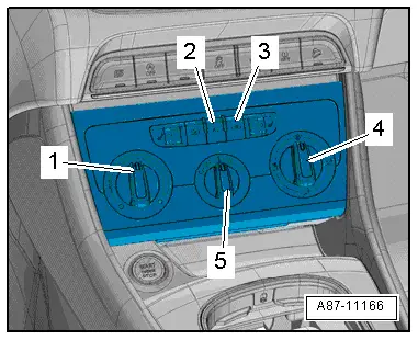
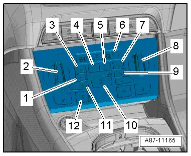
- For vehicles with an automatic climate control system, adjust the temperature setting for the driver- and front passenger side to "warm" via the knobs -2 and 8- on the Climatronic Control Module -J255- control head.
- "HI" in the display -6- on the Climatronic Control Module -J255-.
- Remove the instrument panel. Refer to → Body Interior; Rep. Gr.70; Instrument Panel; Instrument Panel, Removing and Installing.
- Loosen the central tube from the vehicle and slide it a bit toward the rear or remove it. Refer to → Body Interior; Rep. Gr.70; Instrument Panel Central Tube; Instrument Panel Central Tube, Removing and Installing.
 Note
Note
For RHD vehicles, the central tube must always be removed. Refer to → Body Interior; Rep. Gr.70; Instrument Panel Central Tube; Instrument Panel Central Tube, Removing and Installing.
- Remove the driver footwell vent. Refer to → Chapter "Driver Side Footwell Vent, Removing and Installing".
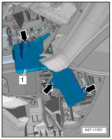
- Remove the bolts -arrows-.
- Remove the heater core cover -1-.
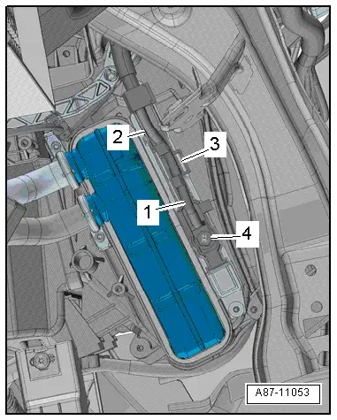
- Remove the nut -4- and then remove the ground cable -1-.
- Release the tab -3- to disconnect the connector -2-.
- Remove the bolt -arrows-.
 WARNING
There is a risk of burns.
- If the Auxiliary Heater Heating Element -Z35- was in operation before being removed, it may still be hot.
- Do not touch the hot radiating surface of the Auxiliary Heater Heating Element -Z35-.
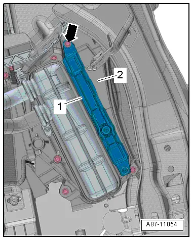
- Remove the heating element -1- from the air distribution housing -2-.
Installing
Installation is done is reverse order, observe the following:
- Clean the heating element area in the shaft before installing.
- Secure/install the central tube. Refer to → Body Interior; Rep. Gr.70; Instrument Panel Central Tube; Instrument Panel Central Tube, Removing and Installing.
- Install the instrument panel. Refer to → Body Interior; Rep. Gr.70; Instrument Panel; Instrument Panel, Removing and Installing.
- Install footwell vent on the driver side. Refer to → Chapter "Driver Side Footwell Vent, Removing and Installing".
After completing the repair work, perform the following operations on the control head using the Vehicle Diagnostic Tester in the "Guided Fault Finding" function:
- Check the DTC memory and delete any currently displayed entries.
- Check the activation and function via the engine control module. Refer to Vehicle Diagnostic Tester in the "Guided Fault Finding" function (for the engine control module).
READ NEXT:
 Heater and A/C Unit, Removing and Installing
Special tools and workshop equipment
required
Hose Clamps - Up To 25mm -3094-
Engine Bung Set -VAS6122-
Compressed air gun, commercially available
Removing
WARNING
There is a
Air Distribution Housing, Removing and Installing
Removing
- Remove the Air Conditioning (A/C) unit (heater). Refer to
→ Chapter "Heater and A/C Unit, Removing and Installing".
- Remove the bolts -arrows-.
- Remove the heate
Heater Core, Removing and Installing
Special tools and workshop equipment
required
Hose Clamps - Up To 25mm -3094-
Engine Bung Set -VAS6122-
Compressed air gun, commercially available
Note
Depending on the engine v
SEE MORE:
Exterior lighting
Switching the lights on and off
Fig. 37 Instrument panel: light button module
Light switch
Press and hold 1 until the desired light function
is selected. The selected function is displayed
briefly in the instrument cluster. When switching
on the ignition, the AUTO light function is automaticall
Overview - Center Console
Overview - Center Console, Basic Equipment Level
1 - Storage Compartment
Vehicles with:
With External Audio Source Connection -R199-
Removing and installing. Refer to
→ Chapter "Front Center Console Storage Compartment, Removing and
Installing".
Insert in the mas
