Audi Q3: Brake Lamp Switch, Removing and Installing
 Note
Note
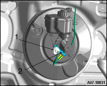
The Brake Lamp Switch -F-/Brake Pedal Switch -F63- is installed in the brake master cylinder.
Removing
Audi RS Q3:
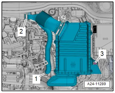
- Remove the air filter housing, refer to → Engine Mechanical, Fuel Injection and Ignition; Rep. Gr.24; Air Filter; Air Filter Housing, Removing and Installing.
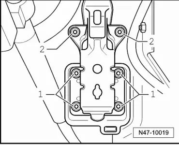
Continuation for All Vehicles:
- Disconnect the connector -1-.
- Remove the brake lamp switch bolt -2-,
- Remove the brake lamp switch down from the brake master cylinder and remove it upward from the retaining tab.
Installing
Install in reverse order of removal. Note the following:
 Note
Note
The brake light switch is not adjusted.
- Make sure that the brake lamp switch is seated correctly at top in the retaining tab.
- Tighten the brake lamp switch bolt.
Brake Booster, Removing and Installing
Special tools and workshop equipment required
- Brake Charger/Bleeder Unit -VAS5234- with Brake Bleeder Adapter -VAS5234/1-
- Sealing plugs from Repair Kit -1H0 698 311 A-
Removing
- Remove the vacuum in the brake booster by pressing the brake pedal repeatedly.
- Remove the air filter housing, refer to → Engine Mechanical, Fuel Injection and Ignition; Rep. Gr.24; Air Filter; Air Filter Housing, Removing and Installing or → Rep. Gr.23; Air Filter Housing, Removing and Installing.
Audi Q3:
- Remove the battery and the battery tray, refer to → Electrical Equipment; Rep. Gr.27; Battery; Battery Tray, Removing and Installing.
Continuation for All Vehicles:
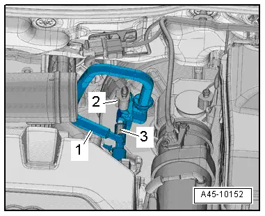
- Disconnect the connector -2-.
- Remove the vacuum line -1- from the vacuum pump and brake booster. Set it aside with the vacuum hose connected.
 Note
Note
A vehicle with a 2.0L TFSI engine is shown in the illustration.
Vehicles with 2.0L TDI engine:
- Tie the air guide hose from the air filter housing to the turbocharger off to the side.
- Loosen the screw-type clamp on the air guide hose between the air guide pipe and turbocharger and turn it toward the rear.
Continuation for All Vehicles:
- Remove the brake master cylinder with the brake fluid reservoir, refer to → Chapter "Brake Master Cylinder, Removing and Installing".
- Disconnect the brake pedal from brake booster, refer to → Chapter "Brake Pedal, Removing from Brake Booster".
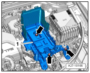
- Remove the nuts -1-.
- Remove the brake booster.
 Note
Note
Ignore item -2-.
Installing
Install in reverse order of removal. Note the following:
- Attach the brake pedal to the brake booster, refer to → Chapter "Brake Pedal, Attaching to Brake Booster".
- Install the brake master cylinder, refer to → Chapter "Brake Master Cylinder, Removing and Installing".
- Bleed the brake system, refer to → Chapter "Hydraulic System, Bleeding".
- If applicable, bleed the clutch mechanism, refer to → Rep. Gr.30; Clutch Mechanism; Clutch Mechanism, Bleeding.
 WARNING
Risk of accident!
Make sure the brakes are working correctly before driving the vehicle.
Tightening Specifications
- Battery tray and battery, refer to → Electrical Equipment; Rep. Gr.27; Battery; Overview - Battery.
READ NEXT:
 Brake Master Cylinder, Removing and Installing
Special tools and workshop equipment
required
Brake Charger/Bleeder Unit -VAS5234-
Sealing plugs from Repair Kit -1H0 698 311 A-
Removing
- Remove the brake fluid reservoir,
Overview - Electric Vacuum Pump
1 - Brake System Vacuum Pump -V192-
Allocation, refer to the Parts Catalog.
Installed location: in the engine compartment over the engine
transmission separating point.
Do not di
Check Valve, Checking
Check valve is removed, refer to
→ Chapter "Check Valve, Removing and Installing".
Note
The check valve is installed directly in front of the vacuum
pump.
Valve must all
SEE MORE:
Electronic Stabilization Control
Description
Electronic Stabilization Control (ESC) supports
driver safety. It reduces the risk of slipping and
improves driving stability. ESC detects critical situations,
such as if the vehicle is over steering or
under steering, or if the wheels are spinning. The
brakes are applied or the motor to
Inner Window Shaft Strip, Removing and Installing
Removing
- Remove the front window frame trim panel. Refer to
→ Body Interior; Rep. Gr.70; Front Door Trim; Window Frame Trim
Removing and Installing.
- Remove the window shaft strip -1-
upward -arrows-.
Installing
Install in reverse order of removal. Note the f
