Audi Q3: Component Location Overview - Components Inside Front Passenger Compartment
Component Location Overview - Components Inside Front Passenger Compartment, Left Side of Passenger Compartment
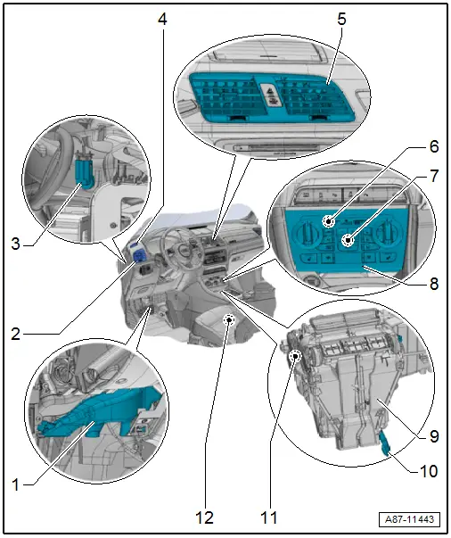
1 - Left Footwell Vent
- Overview. Refer to → Chapter "Overview - Air Routing and Air Distribution in Passenger Compartment, Front Air Guides".
2 - Left Instrument Panel Vent
- Removing and installing. Refer to → Body Interior; Rep. Gr.70; Instrument Panel; Instrument Panel Vent, Removing and Installing.
3 - Left Vent Temperature Sensor -G150-
- Only with an automatic climate control system
- Check in the "Guided Fault Finding" function. Refer to Vehicle Diagnostic Tester
- Removing and installing. Refer to → Chapter "Left Vent Temperature Sensor -G150-, Removing and Installing".
4 - Defroster Vent for the Left Side Window
- Removing and installing. Refer to → Body Interior; Rep. Gr.70; Instrument Panel; Side Defroster Vent, Removing and Installing.
5 - Center Instrument Panel Vent
- Removing and installing. Refer to → Body Interior; Rep. Gr.70; Instrument Panel; Instrument Panel Vent, Removing and Installing.
6 - Instrument Panel Temperature Sensor -G56-
- Only with an automatic climate control system
- Is integrated in the Climatronic Control Module -J255- and cannot be replaced separately
7 - Interior Temperature Sensor Fan -V42-
- Only with an automatic climate control system
- Installed in the Climatronic Control Module -J255- control head
- Removing and installing. Refer to → Chapter "Interior Temperature Sensor Fan, Removing and Installing ".
8 - A/C (Heater) Control Head
- There are different versions. Refer to the Parts Catalog.
Manual climate control system (heater without A/C system)
- For general information, refer to → Chapter "General Information for A/C Control Module -J301- Control Head - Manual Climate Control System".
- A/C Control Module -J301- (Heater Control Module -J65-), removing and installing. Refer to → Chapter "Display and Control Head, Removing and Installing, A/C Control Module -J301- (Heater Control Module -J65-)".
Automatic climate control system
- For general information, refer to → Chapter "General Information for Climatronic Control Module -J255- Control Head - Automatic Climate Control System".
- Climatronic Control Module -J255-, removing and installing. Refer to → Chapter "Display and Control Head, Removing and Installing, Climatronic Control Module -J255-".
9 - A/C Unit (View From Left)
- There are different versions. Refer to the Parts Catalog.
- Air distribution system block diagram. Refer to → Chapter "Air Intake and Outlet Openings".
- Overview. Refer to → Chapter "Overview - Heater and A/C Unit Attachments and Air Intake Housing".
- Removing and installing. Refer to → Chapter "Heater and A/C Unit, Removing and Installing".
10 - Condensation Water Drain
- Checking. Refer to → Chapter "Condensation Water Drain, Checking".
- Removing and installing. Refer to → Chapter "Condensation Water Drain, Removing and Installing".
11 - Left Footwell Vent Temperature Sensor -G261-
- Only with an automatic climate control system
- Removing and installing. Refer to → Chapter "Left Footwell Vent Temperature Sensor -G261-, Removing and Installing".
12 - Left Front Seat
- Equipment level with seat heating
- There are different versions. Refer to the Parts Catalog.
- The seat heating is set on the Climatronic Control Module -J255-/A/C Control Module -J301- (the Heater Control Module -J65-) control head
- Check activation and function. Refer to → Chapter "Seat Heating".
- Seat heating, servicing. Refer to → Body Interior; Rep. Gr.74; Front Seat Covers and Cushions; Overview - Seat Heating Element.
Component Location Overview - Components Inside Front Passenger Compartment, Right Side of Passenger Compartment
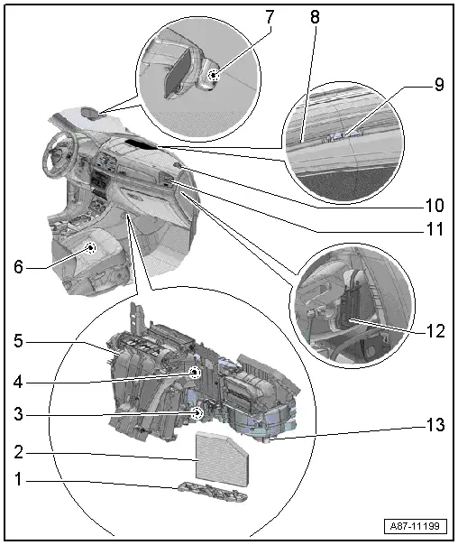
1 - Dust and Pollen Filter Shaft Cover
2 - Dust and Pollen Filter
- There are different versions. Refer to the Parts Catalog.
- Notes on the version with activated charcoal element. Refer to → Chapter "Dust and Pollen Filter Information".
- Replacement intervals. Refer to →Maintenance Intervals; Rep. Gr.03.
- Removing and installing. Refer to → Chapter "Dust and Pollen Filter, Removing and Installing".
3 - Evaporator Vent Temperature Sensor -G263-
- Removing and installing. Refer to → Chapter "Evaporator Vent Temperature Sensor -G263-, Removing and Installing".
4 - Right Footwell Vent Temperature Sensor -G262-
- Only with an automatic climate control system
- Removing and installing. Refer to → Chapter "Right Footwell Vent Temperature Sensor -G262-, Removing and Installing".
5 - A/C Unit (View From Right)
- There are different versions. Refer to the Parts Catalog.
- Air distribution system block diagram. Refer to → Chapter "Air Intake and Outlet Openings".
- Overview. Refer to → Chapter "Overview - Heater and A/C Unit Attachments and Air Intake Housing".
- Removing and installing. Refer to → Chapter "Heater and A/C Unit, Removing and Installing".
6 - Right Front Seat
- Equipment level with seat heating
- There are different versions. Refer to the Parts Catalog.
- The seat heating is set on the Climatronic Control Module -J255-/A/C Control Module -J301- (the Heater Control Module -J65-) control head
- Check activation and function. Refer to → Chapter "Seat Heating".
- Seat heating, servicing. Refer to → Body Interior; Rep. Gr.74; Front Seat Covers and Cushions; Overview - Seat Heating Element.
7 - Humidity Sensor -G355-
- There are different versions. Refer to the Parts Catalog.
- Installed in the mirror base
- To check, use the Vehicle Diagnostic Tester in the "Guided Fault Finding" function
- Removing and installing. Refer to → Chapter "Humidity Sensor -G355-, Removing and Installing".
 Note
Note
The Climatronic Control Module -J255- control head currently only evaluates the Humidity Sensor -G355- on vehicles with an automatic climate control system.
8 - Windshield Defroster Vent
- Removing and installing. Refer to → Body Interior; Rep. Gr.70; Instrument Panel; Instrument Panel Vent, Removing and Installing.
9 - Sunlight Photo Sensor -G107-
- Only with an automatic climate control system
- To check the sunlight measured by the Sunlight Photo Sensor -G107- and calculated by the Climatronic Control Module -J255- control head, use the "Read measured values" function on the Vehicle Diagnostic Tester in the "Guided Fault Finding" function.
- Removing and installing. Refer to → Chapter "Sunlight Photo Sensor -G107-, Removing and Installing".
10 - Defroster Vent for the Right Side Window
- Removing and installing. Refer to → Body Interior; Rep. Gr.70; Instrument Panel; Side Defroster Vent, Removing and Installing.
11 - Right Instrument Panel Vent
- Removing and installing. Refer to → Body Interior; Rep. Gr.70; Instrument Panel; Instrument Panel Vent, Removing and Installing.
12 - Right Vent Temperature Sensor -G151-
- Only with an automatic climate control system
- To check, use the Vehicle Diagnostic Tester in the "Guided Fault Finding" function
- Removing and installing. Refer to → Chapter "Right Vent Temperature Sensor -G151-, Removing and Installing".
13 - Fresh Air Blower -V2-
- There are different versions. Refer to the Parts Catalog.
- Overview. Refer to → Chapter "Overview - Heater and A/C Unit Attachments and Air Intake Housing, Fresh Air Blower, Cover".
READ NEXT:
 System Overview - Refrigerant Circuit
HD = High-pressure end
ND = Low-pressure end
1 - A/C Compressor Regulator Valve -N280-
To check, refer to Vehicle Diagnostic Tester in the "Guided Fault
Finding" function,
→&nb
Overview - Condenser
Overview - Condenser, Dryer Cartridge
Note
There are different versions of the condenser, radiator and
auxiliary radiator. Observe the correct allocation of these components.
Refer t
SEE MORE:
Overview - Trim Molding and Covers
1 - Front Door Gap Cover
Removing and installing. Refer to
→ Chapter "Door Gap Cover, Removing and Installing".
2 - Clip
Quantity: 5
3 - Grommet
For the clip
4 - Front Door
5 - Side Window
6 - Trim Strip
Refrigerant Lines, Disconnecting and Connecting at A/C Compressor
Special tools and workshop equipment
required
Wrench - Door Adjusting - Joint -3320/1-
Engine Bung Set -VAS6122-
WARNING
Danger due to refrigerant coming out under pressure.
Danger of frost bite to skin and other parts of the
body.
Extract the refrigerant and immediately
