Audi Q3: Overview - Condenser
Overview - Condenser, Dryer Cartridge
 Note
Note
- There are different versions of the condenser, radiator and auxiliary radiator. Observe the correct allocation of these components. Refer to the Parts Catalog.
- The "Modine" condenser is shown in the illustration.
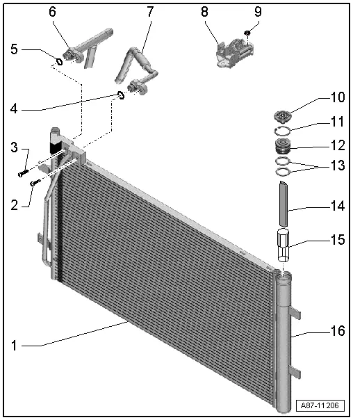
1 - Condenser
- There are different versions. Refer to the Parts Catalog.
- Refrigerant line, disconnecting and reconnecting. Refer to → Chapter "Refrigerant Lines, Disconnecting and Connector at Condenser".
- Removing and installing. Refer to → Chapter "Condenser, Removing and Installing".
2 - Bolt
- 9 Nm
3 - Bolt
- 9 Nm
4 - O-ring seal
- Replacing. For the correct version, refer to the Parts Catalog.
- Coat with refrigerant oil before installing. Refer to → Chapter "Refrigerant Circuit Seals".
5 - O-ring seal
- Replacing. For the correct version, refer to the Parts Catalog.
- Coat with refrigerant oil before installing. Refer to → Chapter "Refrigerant Circuit Seals".
6 - Refrigerant line
- To the A/C compressor
7 - Refrigerant line
- to the expansion valve
- With a branch to the high pressure side service connection
- Equipment levels with connection point
8 - Bracket
- for the refrigerant lines
9 - Nut
- 2.5 Nm
- Quantity: 2
10 - Cap
- There are different versions. Refer to the Parts Catalog.
11 - Circlip
12 - Cap/Sealing Plug
- 2 Nm
- There are different versions. Refer to the Parts Catalog.
- With O-ring seals
- Replace the cap if it is damaged
- Coat the O-ring seal with refrigerant oil before installing. Refer to → Chapter "Refrigerant Circuit Seals".
13 - O-Ring Seals
- Replacing. For the correct version, refer to the Parts Catalog.
- Coat with refrigerant oil before installing. Refer to → Chapter "Refrigerant Circuit Seals".
14 - Dryer Cartridge
- There are different versions. Refer to the Parts Catalog.
- Removing and installing. Refer to → Chapter "Dryer Bag/Dryer Cartridge, Removing and Installing".
15 - Strainer
- There are different versions. Refer to the Parts Catalog.
- Removing and installing. Refer to → Chapter "Dryer Cartridge, Removing and Installing, Modine Condenser".
16 - Receiver/Dryer
- There are different versions. Refer to the Parts Catalog.
- removing and installing:
- Showa/Keihin condenser. Refer to → Chapter "Receiver/Dryer, Removing and Installing".
 Note
Note
Depending on the version, the receiver/dryer is either completely replaced or only the dryer cartridge is replaced on the Showa/Keihin condenser.
Overview - Condenser, A/C Compressor, Expansion Valve, Refrigerant Line
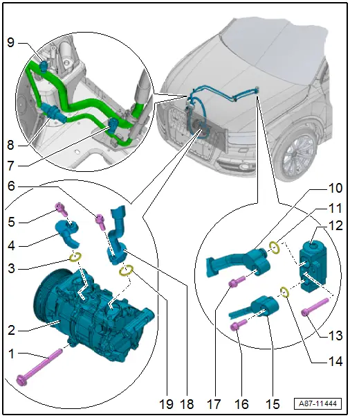
1 - Bolt
- Quantity: 3
- There are different versions. Refer to the Parts Catalog.
- Tightening specification for steel bolts: 25 Nm
- Tightening specification for aluminum bolts: 8 Nm + 180º turn
- Only use aluminum bolts once, then replace.
2 - A/C Compressor
- There are different versions. Refer to the Parts Catalog.
- Refrigerant line, disconnecting and reconnecting. Refer to → Chapter "Refrigerant Lines, Disconnecting and Connecting at A/C Compressor".
- Removing and installing. Refer to → Chapter "A/C Compressor, Removing and Installing on Bracket".
- Belt pulley, removing and installing, overview. Refer to → Chapter "Overview - Belt Pulley".
3 - O-Ring Seal
- Replacing. For the correct version, refer to the Parts Catalog.
- Coat with refrigerant oil before installing. Refer to → Chapter "Refrigerant Circuit Seals".
4 - Refrigerant Line
- to the condenser
- Equipment levels with connection point
5 - Bolt
- 22 Nm
6 - Bolt
- 22 Nm
7 - High Pressure Side Service Connection
 Caution
Danger due to refrigerant coming out under pressure when there is a defective valve in the refrigerant circuit.
Danger of frost bite to skin and other parts of the body.
Only remove when the refrigerant circuit is empty. The connection does not have a valve. Refer to → Refrigerant R134a Servicing; Rep. Gr.87; A/C System, General Information (Refrigerant R134a Servicing; A/C System, General Information).
- Removing and installing. Refer to → Chapter "Service Connection on Low and High Pressure Side, Removing and Installing".
8 - High Pressure Sensor -G65-
- To check, refer to Vehicle Diagnostic Tester in the "Guided Fault Finding" function, → Chapter "High Pressure Sensor -G65-, Checking Pressure Signal" and → Wiring diagrams, Troubleshooting & Component locations.
- Removing and installing. Refer to → Chapter "High Pressure Sensor -G65-, Removing and Installing".
- 8 Nm
9 - Low Pressure Side Service Connection
 Caution
Danger due to refrigerant coming out under pressure when there is a defective valve in the refrigerant circuit.
Danger of frost bite to skin and other parts of the body.
Only remove when the refrigerant circuit is empty. The connection does not have a valve. Refer to → Refrigerant R134a Servicing; Rep. Gr.87; A/C System, General Information (Refrigerant R134a Servicing; A/C System, General Information).
- Removing and installing. Refer to → Chapter "Service Connection on Low and High Pressure Side, Removing and Installing".
10 - Refrigerant Line
- to the expansion valve
- Equipment levels with connection point
11 - O-Ring Seal
- Replacing. For the correct version, refer to the Parts Catalog.
- Coat with refrigerant oil before installing. Refer to → Chapter "Refrigerant Circuit Seals".
12 - Expansion Valve
- There are different versions. Refer to the Parts Catalog.
- Refrigerant line, disconnecting and reconnecting. Refer to → Chapter "Refrigerant Lines, Disconnecting and Connecting at Expansion Valve".
- Removing and installing. Refer to → Chapter "Expansion Valve, Removing and Installing".
13 - Bolt
- Quantity: 2
- 10 Nm
14 - O-Ring Seal
- Replacing. For the correct version, refer to the Parts Catalog.
- Coat with refrigerant oil before installing. Refer to → Chapter "Refrigerant Circuit Seals".
15 - Refrigerant Line
- from the A/C compressor
16 - Bolt
- 10 Nm
17 - Bolt
- 10 Nm
18 - Refrigerant Line
- From the condenser
- Equipment levels with connection point
19 - O-Ring Seal
- Replacing. For the correct version, refer to the Parts Catalog.
- Coat with refrigerant oil before installing. Refer to → Chapter "Refrigerant Circuit Seals".
READ NEXT:
 High Pressure Sensor -G65-, Removing and Installing
Note
When the High Pressure Sensor -G65- is removed, the cooling
output cannot be checked. The Climatronic Control Module
-J255-/A/C Control Module -J301- control head does not switch
Expansion Valve, Removing and Installing
Special tools and workshop equipment
required
Engine Bung Set -VAS6122-
Removing
- Remove the refrigerant pipes from the expansion valve. Refer
to
→ Chapter "Refrigerant Line
Receiver/Dryer, Removing and Installing
WARNING
Danger due to refrigerant coming out under pressure.
Danger of frost bite to skin and other parts of the
body.
Extract the refrigerant and immediately open the
refrigerant
SEE MORE:
Overview - Antenna Systems
The antenna system consists of the Roof Antenna -R216- and
the window antenna.
Roof Antenna -R216-
GPS Antenna -R50-, only on 7T2, 7T6 and 7Q4
Telephone Antenna -R65-, only on 9ZF and 9ZW
Satellite Antenna -R170-, only North America and QV8
Auxiliary Heater Antenna -R182-, only Europe a
Maintenance
Fluid Capacity Tables
Maintenance, diagnosis
Audi Q3
Caution
All quantities are approximate. Always refer to the
Repair Manual and/or the Maintenance Procedures for
correct filling instructions.
Refer to Technical Bulletin 2010043 for engine oils
meeting the required Audi oil qu
